
User Guide

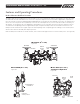

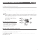


Seat Ring Assembly Removal (See pages 10-11)
Note: Remove the seat ring assembly only if the seat ring (item 3) or arm (item 4) appear to be worn or damaged.
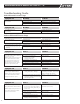
1. Remove locknuts (item 3.4) and washers (item 3.3). (See Figure #4 below.)
2. Remove seat ring assembly.
NOTE: When reassembling, tighten locknuts to 12 - 15 ft./lbs. If leaking occurs around bolt, further tighten until leaking stops. Do not over
tighten.
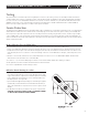
3. Remove retaining clip (item 5) from one end of the swing pin (item 4.2). Hold arm (item 4) while sliding out swing pin (item 4.2). Inspect
bushings (item 4.1) and pin (item 4.2) for wear or damage. Replace if necessary. Inspect gasket (item 3.l) for debris and/or damage. Replace
if necessary.
Note: Reverse the procedure above to reassemble the components. Seat ring will only fit into body one way. Check alignment of seat ring if
studs don’t align with body holes. Gasket is also non-symmetric. Both seat ring and gasket have a notch that indicates non-symmetric
hold. Clean all parts thoroughly with clean water
before reassembly. Reassemble and bleed test
cocks #4 and #3. Repressurize the assembly
and test assembly in accordance with the locally
approved test method.
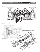
Relief Valve Removal (See pages 10-11)
1. Remove capscrews (item 24), washers (item 24.1) and
nuts (item 25) at base of relief valve body and hydraulic
sensing port. Remove relief valve seat ring (item 34) from
bottom of relief valve. Inspect seat ring (item 34), seat
disc (item 32), and guide (item 33) for debris, wear, or
damage. Replace as necessary. (See below.)
Relief Valve Seat Disc Replacement (See pages 10-11)
1. Separate relief valve from elbow and sensing line flange. Remove cover bolts (item 22) and cover (item 20).
2. Lift out diaphragm (item 37) and inspect for damage. Replace if necessary.
3. Grasp spring button (item 28) and pull out relief valve module.
4. Turn over relief valve assembly module so that guide (item 33) stem is facing up. Use tabs on guide (item 33) to loosen guide. Unscrew
guide and replace seat disc (item 32).
5. Reassemble in reverse order.
Seat Ring
Figure #4
7
MAINTENANCE MANUAL MODELS 860 & 880V 2
1
/2" – 10"
IOM-F-860_880V.indd 7 7/11/08 10:45:27 AM