
User Guide


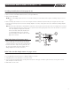


Relief Valve Disassembly (See pages 10-11)
1. Remove o-ring (item 34.1) and RV seat ring (item 34) from the bottom of RV body.
2. Remove RV cover (item 20) from RV body by removing eight capscrews (item 22).
3. Remove diaphragm from RV body. Remove RV assembly module from RV body (item 21).
4. Loosen tabs on guide (item 33) and remove guide and seat disc (item 32), remove instruction label
(item 28.2) from center of button, covering flow screw (item 28.1).
5. Loosen flow screw (item 28.1). CAUTION spring is captured. Remove spring (item 29) from main guide
(item 31), remove flow washer (item 30) from top of diaphragm (item 37).
6. Remove stem (item 30) and stem washer (item 30.1), on end of stem, from diaphragm guide assembly.
7. Unscrew retainer from main guide (item 31) and remove slip ring (item 38.1) from retainer.
8. Remove small diaphragm (item 37) from main guide (item 31).
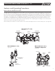
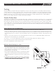
Relief Valve Assembly (See pages 10-11)
Note: Clean all parts thoroughly with clean water before reassembly.
1. Place small diaphragm (item 37) into main guide (item 31) with beaded side of flange pointed down.
2. Drop slip ring (item 38.1) into retainer (item 38) and screw retainer into main guide (item 31) as shown, being careful not to bind the dia-
phragm’s cup shape with your finger.
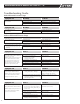
3. Place stem washer (item 32) on end of stem (item 30) and insert stem into diaphragm guide assembly. When the stem is fully inserted it
does not bottom out against diaphragm, so do the following: Press diaphragm against stem with your thumb and forefinger and slowly pull
the stem back out with the diaphragm. Place stem guide assembly on bench with diaphragm pointed up.
4. Place flow washer (item 39) on top of diaphragm (item 37) with slots facing up and with holes lining up.
Set spring (item 29) on main guide (item 31) and compress spring with button (item 28). With spring fully compressed insert and tighten
down flow screw (item 28.1), being careful not to twist button or assembly which will distort the diaphragm.
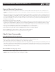
5. Stick instruction label (item 28.2) in center of button, covering flow screw (item 28.1). Install seat disc
(item 32) into stem (item 30) and install guide (item 33) to retain disc. Using tabs on guide, tighten until shoulder on guide contacts stem.
6. Lubricate o-ring (item 31.1) with supplied lubricant and install on main guide (item 31).
7. Install assembly into relief valve body (item 21). Place large diaphragm (item 27), with cap facing down,
into RV body and fold over stem assembly button. Pull diaphragm flange up onto RV body flange.
8. Assemble RV cover (item 20) to RV body using eight capscrews (item 22) and tighten to 120 inch-pound torque wrench limit.
9. Insert RV seat ring (item 34) into bottom of RV body (aligning it with guide (item 33) and install o-ring (item 34.1).
N-SHAPE (V) ONLY - Assemble complete relief valve assembly to valve body as shown with o-ring
(item 35) and back-up ring (item 35.1), using four capscrews (item 24), eight washers (item 24.1) and four nuts (item 25). Tighten to 120
inch-pounds torque wrench limit. Attach sensing line flange cover (item 36).
Do not over tighten.
IN-LINE ONLY - Assemble completed unit to valve body and elbow with gasket (item 26) install with screen facing valve body) using six
capscrews (item 24), twelve washers (item 24.1) and six nuts (item 25). Tighten to 120 inch-pounds torque wrench limit. Do not over
tighten.
8
MAINTENANCE MANUAL MODELS 860 & 880V 2
1
/2" – 10"
IOM-F-860_880V.indd 8 7/11/08 10:45:27 AM