
User Guide


Testing
All mechanical devices should be inspected on a regular basis to ensure they are working correctly. The assembly should be tested at time
of initial installation, after servicing or maintenance, and at least annually thereafter. Acceptable test procedures are published by Foundation
for Cross Connection Control and Hydraulic Research at the University of Southern California (USC), The American Water Works Association
(AWWA), The American Society of Sanitary Engineering (ASSE Series 5000) and the Canadian Standards Association (CAN/CSA B64.10).
Please consult the regulatory authority in your area for more specific information.
Freeze Protection
The Reduced Pressure Backflow Prevention Assembly may be subject to damage if the internal water is allowed to freeze. It is suggested that
all assemblies be installed with resilient seated shutoffs so that a drip tight closure can be achieved to prevent refilling of the assembly after
the freeze protection procedure is performed. The unit must be protected from freezing using a heated enclosure, insulation using heat tape,
or other suitable means. If the system will be shut down during freezing weather, use the following procedure to drain internal passages. A
system should have a shutoff valve located upstream of freeze protection area, and a means for draining upstream of the #1 shutoff and down-
stream of the #2 shutoff valve.
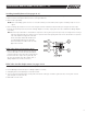
Reduced Pressure Zone and Relief Valve
For more detailed instructions on freeze protection procedures request “Freeze Protection Instructions for RP Devices.”
1. Slowly close supply valve upstream of freeze protected area, open all test cocks on the backflow preventer. All water within the zone will
be drained to the lowest point of the relief valve discharge port (relief valve seat). A small amount of water will remain in the bottom of the
main valve body, but this is not sufficient to cause freeze damage. Leave test cocks and ball valves in half open, half closed position for the
winter.
2. All water on the inlet side, and within the zone, will be drained down to the #1 test cock on the Model 880 and 880V. All water will be
drained from the inlet side and the zone of the Model 860.
3. For sizes 2
1
/2" - 10", remove both drain plugs from bottom of relief valve assembly. Replace when draining is complete.
4. Drain upstream of the #1 shutoff valve and downstream of the #2 shutoff valve.
5. Proceed to step 6 Ball Valve Shutoff Draining Procedure.
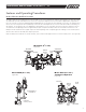
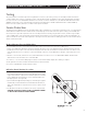
Ball Valve Shutoff Draining Procedure
6. If the assembly has been installed with ball valve shutoff valves, they
must also be properly drained to prevent freeze damage. After the drain-
ing procedure has been completed on the backflow prevention assembly,
position all ball valve shutoffs and test cocks in a half open/half closed
(45 degree) position. (see Figure #5)
7. Open the ball valve approximately 45 degrees, while draining the pipeline
and assembly, to allow water between the ball valve and valve body to
drain. Leave the ball valve in this position for the winter to prevent freeze
damage.
8. The ball valves must be fully closed before the system is repressurized.
OPEN AND CLOSE BALL VALVES SLOWLY TO PREVENT DAMAGE
TO THE SYSTEM CAUSED BY WATER HAMMER.
Ball Valve
1
/2" - 2"
Figure #5
9
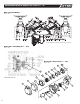
MAINTENANCE MANUAL MODELS 860 & 880V 2
1
/2" – 10"
IOM-F-860_880V.indd 9 7/11/08 10:45:27 AM