
Install Instructions
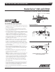

Typical Installation
Figure 1
Figure 2
IS-F-860RPZ
INSTALLATION INSTRUCTIONS
MasterSeries
®
860 and LF860
Reduced Pressure Zone Assemblies
Sizes:
1
⁄2" – 2" (15 - 50mm)
860
Installation Instructions
1. Consult local codes for specific installation requirements and restrictions
applicable to your area. It is recommended that system supply pressure
be at least 20 psi (138 kPa).
2. These instructions apply to models 860, LF860, 860U, and LF860U
sizes
1
⁄2" - 2" (15 - 50mm) only. The valves may be installed only in the
orientation/flow direction as shown.
3. THE VALVE ASSEMBLY MUST BE INSTALLED WHERE RELIEF VALVE
DISCHARGE WILL BE ACCEPTABLE, OR WHERE RELIEF DISCHARGE
CAND BE COMPLETELY DRAINED. The valve assembly must be
installed where it is accessible for periodic testing and maintenance.
Clearances shown in the installation views apply to exterior, interior and
pit/vault installations and are only recommendations. These minimums
do not apply to removable protective enclosures. Refer to local codes
for actual requirements in your area.
Note: The gap drain is not designed to catch the maximum discharge
possible from the relief valve. The installation of FEBCO air gap with
the drain line terminating above a floor drain will handle any normal
discharge or nuisance spitting through the relief valve. However, floor
drain size may need to be designed to prevent water damage caused by
a catastrophic failure condition. Do not reduce the size of the drain line
from the air gap fitting.
4. PRIOR TO INSTALLING THE VALVE INTO THE LINE, FLUSH THE
SUPPLY LINE OF ALL FOREIGN MATERIAL. Failure to flush the supply
line may cause the check valves to become fouled and require disas-
sembly and cleaning.
5. After installation SLOWLY fill the assembly with water and bleed air
from the body using the #2, # 3 and # 4 test cocks. Test the valve
assembly to ensure correct operation.
NOTE: All assemblies are tested at the factory for proper operation and
leakage. If the valve does not pass the field test, it is most likely due
to a fouled check valve. This is not covered by the factory warranty.
The valve cover must be removed and the check seats inspected and
cleaned. Any damage or improper operation caused by pipeline debris or
improper installation/start-up is not included inthe factory warranty.
In case of a possible warranty claim, contact your local supplier or
FEBCO Representative. DO NOT REMOVE THE VALVE ASSEMBLY
FROM THE PIPELINE.
6. The assembly must be protected from freezing and excessive pressure
increases. Thermal expansion or water hammer can cause pressure
increases. These excessive pressure situations must be eliminated to
protect the valve and system from possible damage.
7. Plastic testcock plugs and tethers are provided (loose in box) for areas
that require them.
12" Min (300mm)
Flow
12" Min (300mm)
3" Min (75mm)
18" Min (450mm)
HORIZONTAL INSTALLATION OF THE SERIES 860, LF860
(Top view, shown with strainer)