
Design Double Check Detector Assemblies Manual

2
ENGLISH INSTRUCTIONS
Installation Instructions
1. Consult local codes for specific installation
requirements and restrictions applicable to
your area. It is recommended that system
supply pressure be at least 20psi (138 kPa).
2. These instructions apply to Series
870V/876V, and LF870V/LF876V/876VST
sizes 2
1
⁄2" to 10" (65-250mm) only. The
valves may be installed only in the orienta-
tion/flow direction as shown. All 870V/876V
and LF870/LF876V/876VST assemblies are
shipped in the horizontal installation orien-
tation only. The gate valves may be rotated
as permitted by the flange bolt pattern.
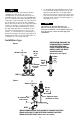
3. The valve assembly must be installed
where it is accessible for periodic testing
and maintenance. Clearances shown in the
installation views apply to exterior, interior
and pit/vault installations and are only rec-
ommendations. These minimums do not
apply to removable protective enclosures.
Refer to local codes for actual requirements
in your area.
4. PRIOR TO INSTALLING THE VALVE INTO
THE LINE, FLUSH THE SUPPLY LINE OF
ALL FOREIGN MATERIAL. Failure to flush
the supply line may cause the check valves
to become fouled and require disassembly
and cleaning.
5. Lift the assembly by connecting lift
hooks to the lift rings cast into the valve
body. DO NOT LIFT THE ASSEMBLY
BY CONNECTING TO THE GATE VALVE
HANDWHEELS OR STEMS. The use of the
optional valve setters (horizontal units only)
provides for a rigid connection to the sup-
ply line (with the correct centerline) without
the need for concrete thrust blocks.
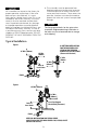
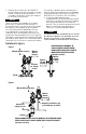
6. For vertical installation, loosen bolts on
the groove coupling just enough to allow
rotation of the outlet check. Rotate outlet
check 180º. Ensure that the vertical support
adapter is in place (valve is shipped with
adapter banded in place) and install pipe
support (pipe support to be furnished by
the customer and shall fit same size pipe
as the valve being installed, except 2
1
⁄2"
(65mm) valves will use a 3" pipe support).
NOTICE
THE VALVE BODY AND PIPE SUPPORT ARE
INTENDED TO SUPPORT THE WEIGHT OF
THE SECOND CHECK VALVE AND OUTLET
GATE VALVE ONLY. THE PIPING ABOVE THE
OUTLET GATE VALVE MUST BE SUPPORTED
INDEPENDENTLY. Retighten bolts of groove
coupling. Rotate outlet gate valve as desired
– required.
6a. For vertical installation of the DCDA, first
remove formed tube from bypass piping,
then follow instructions outlined in No. 6
above. When this has been completed,
rotate the compression fitting elbow 180º
and reinstall the tube, rotating the pipe tee
now at the bottom of the outlet check to
align with tube.
7. After installation SLOWLY fill the assembly
with water and bleed air from the body
using the # 3 and # 4 test cocks. Test the
valve assembly to ensure correct operation.
You are required to consult the local building and plumbing codes prior to installa-
tion. If the information in this manual is not consistent with local building or plumb-
ing codes, the local codes should be followed. Inquire with governing authorities for
additional local requirements.
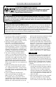
WARNING
!
Need for Periodic Inspection/Maintenance: This product must be tested periodically
in compliance with local codes, but at least once per year or more as service conditions
warrant. All products must be retested once maintenance has been performed. Corrosive
water conditions and/or unauthorized adjustments or repair could render the product
ineffective for the service intended. Regular checking and cleaning of the product’s internal
components helps assure maximum life and proper product function.
WARNING
!
WARNING
!
Read this Manual BEFORE using this equipment.
Failure to read and follow all safety and use information can result in death,
serious personal injury, property damage, or damage to the equipment.
Keep this Manual for future reference.