Installation, Operation and Maintenance MODEL F80A CATEGORY I NATURAL GAS AND LP GAS MID EFFICIENCY WARM AIR FURNACE TABLE OF CONTENTS INTRODUCTION . . . . . . . . . . . . . . . . . . . . . . .1 SAFETY . . . . . . . . . . . . . . . . . . . . . . . . . . . . . .1 CODES . . . . . . . . . . . . . . . . . . . . . . . . . . . . . .2 FURNACE SIZING . . . . . . . . . . . . . . . . . . . . . .3 LOCATION of UNIT . . . . . . . . . . . . . . . . . . . .3 INSTALLATION POSITIONS . . . . . . . . . . . . . . .
MODEL F80A INTRODUCTION This gas fired midefficiency (non-condensing) furnace is an up flow, counterflow or horizontal flow warm air furnace suitable for residential and light commercial heating applications from 35,000 to 135,000 BTU/Hr. This appliance is a CGA / AGA design certified as a Category I chimney vent central forced air furnace with all combustion air supplied from the ambient air around the furnace.
WARM AIR FURNACE DANGER DANGER WHEN THIS FURNACE IS INSTALLED IN A RESIDENTIAL GARAGE, IT MUST BE INSTALLED SO THE BURNERS AND IGNITION SOURCE ARE LOCATED NO LESS THAN 18 INCHES ABOVE THE FLOOR TO PREVENT THE RISK OF IGNITING FLAMMABLE VAPORS WHICH MAY BE PRESENT IN THE GARAGE.
MODEL F80A FURNACE SIZING The maximum hourly heat loss for each heated space shall be calculated in accordance with the procedures described in Manual J titled, "Load Calculation" published by the Air Conditioning Contractors of America, or by any other method which is suitable for local conditions, provided the results obtained are in substantial agreement with, and not less than those obtained using the procedure described in their manual.
WARM AIR FURNACE • If the furnace is to be located in an area where the combustion air is laden with chemical compounds such as bromine, chlorine or fluorine, as may be found in swimming pool chemicals, laundry detergents, etc., use outdoor air for combustion. These compounds when exposed to flame, form acids, which attack the heat exchanger and other components. UPFLOW INSTALLATION This furnace comes assembled for installation in the upflow position and ready for vertical venting.
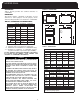
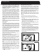
MODEL F80A FIGURE 2: DIMENSIONS CLEARANCES Table 2 (below) provides the certified clearances to combustibles. DIMENSION MODEL K G IMPORTANT: This furnace requires a minimum of 24-inches of front clearance for service purposes. For this purpose, service clearance takes precedence over clearance to combustibles. 35-2 50-3 70-3 70-4 85-3 85-4 100- 4 100-5 115-5 L J F L TABLE 2: CLEARANCES TO COMBUSTIBLES UNIT TOP PLENUM TOP/BOTTOM PLENUM SIDES UPFLOW 1" COUNTERFLOW 0" HORIZONTAL 2" 1" 1" 2.
WARM AIR FURNACE DUCTWORK DUCTWORK STEPS: Proper airflow is required for the correct operation of this furnace. Insufficient airflow may cause erratic operation, could cause the furnace to cycle on the high temperature limit, and may damage the heat exchanger. Excessive airflow may result in an excessively noisy duct system and may result in undesirable consequences such as creating uncomfortable drafts and causing drapes or curtains to blow around. 1.
MODEL F80A NOTE: If using grilles to cover the two openings, factor in the free area of the grille. Typically, a grille will have a free area approximately 50% of its nominal size. Consequently, if the required opening is 10 inches x 10 inches , it will have to be doubled if using a sidewall grille with 50% free area. DETERMING COMBUSTION AIR DANGER READ, UNDERSTAND AND FOLLOW ALL INSTRUCTIONS IN THIS SECTION.
WARM AIR FURNACE FURNACE VENTING DEFINITIONS CAUTION "Vent" and "Chimney" refer to open passageways that convey vent gases from the furnace, or its vent connector, to the outside. Vents and chimneys usually run vertically or nearly vertically. When they serve only one gas appliance, they are called "dedicated" vents or chimneys. When they serve multiple gas appliances, they are called "common" vents or chimneys. "Vent Connector" refers to a pipe or duct that connects the furnace to a vent or chimney.
MODEL F80A 4. Place inducer plate and gasket in desired position and locate mounting holes required. NOTE: INDUCER PLATE AND GASKET MUST BOTH BE ROTATED. NOTE: Any holes not concealed by the inducer gasket require the use of screws to plug the holes. 5. Secure inducer plate to flue box cover using four screws in the correct mounting position. 6. Carefully remove side panel knockout corresponding to the venting application and install knockout underneath top panel using two screws (field supplied). 7.
WARM AIR FURNACE INDUCER ROTATION STEPS ON 35-2, 50-3 (See Figures 5A and 5B below) VENT CONNECTOR The furnace may be vented with a listed single wall or Type B double wall vent connector to a B-Vent or lined masonry chimney. Most United States jurisdictions require a minimum 28-gauge galvanized single wall vent connector. Most Canadian jurisdictions require the vent connector to have corrosion resistance equivalent to 24-gauge galvanized sheet metal. 1. Ensure all power to the furnace is disconnected. 2.
10 FT. MODEL F80A RIDGE 2 FT. MIN 3 FT. MIN VENT TERMINATION DEDICATED VENTING Terminate all vertical vents with a listed vent cap or roof assembly unless local codes require otherwise. Locate the termination in an area free of positive pressure or wind eddies. Eddies may occur when wind swirls over roof peaks. They can cause downdrafts and interfere with normal vent operation. Figure 7 (below) shows a good method to permit dedicated venting making use of B-Vent within a masonry chimney.
WARM AIR FURNACE EXISTING VENT CONSIDERATIONS GAS SUPPLY If this furnace is to replace a Category I type furnace connected to a chimney serving other appliances, steps must be taken to ensure that this furnace and the remaining appliances will vent properly after the removal of the existing furnace. There is a chance that the existing chimney will be too large. Check the size of the existing vent or chimney. It should be sized as though this is a new installation.
MODEL F80A NATURAL TO L.P. GAS CAUTION ENSURE THAT THE MANUAL SHUTOFF VALVE AND GAS VALVE ARE NOT SUBJECTED TO HIGH PRESSURES. DISCONNECT THE MANUAL SHUTOFF VALVE AND GAS VALVE DURING ANY PRESSURE TESTING THAT EXCEEDS 1/2 P.S.I.G. (3.45 KPA). The natural gas inlet supply pressure should be 5 to 7 inches water column (w.c.), 7 inches w.c. is recommended. The L.P. gas inlet supply pressure should be 11 to 14 inches w.c., 12 inches w.c. is recommended.
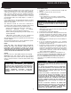
100 115 135 0 - 2000 100,000 80,000 1.95 mm 1.20 mm 2000 - 4500 0 - 2000 2000 - 4500 0 - 2000 2000 - 4500 90,000 115,000 103,500 135,000 121,500 72,000 92,000 82,800 108,000 97,200 1.90 mm 1.95 mm 1.90 mm 1.95 mm 1.90 mm 1.15 mm 1.20 mm 1.15 mm 1.20 mm 1.
MODEL F80A SETTING THE MANIFOLD (Outlet) GAS PRESSURE (F92-1003 36G Valve Pressure Check Kit) 1. 2. 3. 4. 5. 6. 7. Shut off the gas upstream of valve and move valve switch to “OFF”. Using the 3/32 inch hex wrench that is included in the valve pressure check kit, rotate outlet pressure tap screw one revolution counter-clockwise. Attach the 5/16 inch hose that is included in the valve pressure check kit to the outlet pressure boss of the valve. Hose should overlap boss 3/8 inch.
WARM AIR FURNACE LOW VOLTAGE WIRING DANGER THE FURNACE CABINET MUST HAVE AN UNINTERRUPTED GROUND. A GROUND WIRE IS PROVIDED IN THE ELECTRICAL JUNCTION BOX. DO NOT USE GAS PIPING AS A GROUND. FAILING TO GROUND THE FURNACE PROPERLY CAN RESULT IN ELECTRIC SHOCK RESULTING IN PERSONAL INJURY OR DEATH.
MODEL F80A START UP PROCEDURES This furnace is equipped with a hot surface ignition (HSI) device. Each time that the room thermostat calls for heat, the HSI lights the main burners directly. See the lighting instructions on the furnace. TO START THE FURNACE: 1. Remove the burner compartment access door. 2. Shut off the electrical power to the furnace and set the room thermostat to its lowest setting. 3.
VALUES WARM AIR FURNACE CHECKING FURNACE INPUT TEMPERATURE RISE CHECK • The natural gas supply pressure should be a maximum of 7 inches w.c. and minimum of 5 inches w.c. • The burner manifold pressure is normally set to 3.5 inches w.c. for natural gas • The input rating of the furnace is based on 1075 / BTU/cu. ft. gas with a specific gravity of 0.60 Since heating values for the gas vary geographically, the actual furnace input and output will vary accordingly.
MODEL F80A AIRFLOW For proper furnace operation, airflow over the heat exchanger is of utmost importance. Insufficient airflow accelerates metal fatigue and failure in the heat exchanger and excessive airflow promotes accelerated corrosion of the heat exchanger. IMPORTANT: Do not bypass this step of the start up procedures.
WARM AIR FURNACE OPERATING TIPS MAINTENANCE 1. Clean air filters maximize efficiency and reduce heating costs. 2. During the heating season, keep windows and doors closed to reduce the heating load on the system. 3. Avoid excessive use of kitchen exhaust hoods and other exhaust fans to reduce the heating load on the system. 4. Arrange the furniture and drapes so that the supply air registers and return air grilles are unobstructed. 5.
MODEL F80A INDUCED BLOWER ACCESSORIES The induced blower motor should be inspected and cleaned if necessary. Clear any dust buildup from the ventilation ports. FIELD SUPPLIED AND INSTALLED OPTIONAL ACCESSORIES ELECTRONIC AIR CLEANER CIRCULATING FAN The condition of the circulating fan should be checked to ensure that it is free of excessive dust buildup, debris, etc. The mechanical fasteners should be inspected and checked for proper tightness and parts alignment.
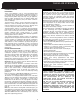
WARM AIR FURNACE TROUBLESHOOTING SEQUENCE OF OPERATION: WHITE RODGERS INTEGRATED FURNACE CONTROL WITH WHITE RODGERS 36G22 GAS VALVE APPLY POWER TO APPLIANCE THERMOSTAT CALLS FOR HEAT NO AIR PROVING SWITCH PROVED OPEN? WAIT FOR AIR PROVING SWITCH TO OPEN YES FIVE MINUTE WAIT PERIOD COMBUSTION AIR BLOWER ON AIR PROVING SWITCH PROVED CLOSED NO COMBUSTION AIR BLOWER OFF YES PREPURGE HOT SURFACE IGNITER ON FOR WARM-UP TIME BETWEEN TRIAL PURGE MAIN VALVE OPENS HOT SURFACE IGNITER OFF MAIN BURNER LI
MODEL F80A 50V51-250 23
WARM AIR FURNACE TABLE 11: GENERAL TROUBLESHOOTING WHITE-RODGERS INTEGRATED FAN CONTROL IF AND CHECK or REPAIR 1. Induced blower wiring. 2. Induced blower. 1. Pressure switch stuck closed. 2. Pressure switch is mis-wired or jumpered. Induced blower does not energize 2 Flash code does not come on Induced blower does not energize 2 Flash code does come on Induced blower is energized 3 Flash code does not come on Wait for the pre-purge to expire.
MODEL F80A FACTORY SETTING R R 3 25
User’s Information Manual MODEL F80A SERIES GAS-FIRED WARM AIR FURNACE TABLE OF CONTENTS FURNACE COMPONENTS . . . . . . . . . . . . . . . . . .1 REGULATOR VENT . . . . . . . . . . . . . . . . . . . . . . .1 GENERAL SAFETY RULES . . . . . . . . . . . . . . . . . .1 FURNACE OPERATION INFORMATION TO START THE FURNACE . . . . . . . . . . . . . .2 FURNACE SHUTDOWN PROCEDURE . . . . .
MODEL F80A FURNACE COMPONENTS GENERAL SAFETY RULES Figure 1 (below) is provided to help identify the components of your furnace. Figure 1: Furnace Components Induced Blower Pressure Switch Limit Switch Gas Valve 1. Combustible materials should not be stored against or around the furnace. Keep the furnace area clear and free from all combustible materials such as newspapers, rags, cardboard, clothing, etc. This applies especially to gasoline and other flammable vapors and liquids. 2.
WARM AIR FURNACE FURNACE SHUTDOWN PROCEDURE FURNACE OPERATION INFORMATION During the heating season, the operation of the furnace is fully automatic. 1. Set the thermostat to its lowest setting. TO START THE FURNACE: 3. Turn the appliance manual shutoff valve to the "OFF" position. 1. First read these instructions and safety notices thoroughly. 2. Set the thermostat to the lowest setting. 3. Ensure that all supply air registers and return air grilles are open. 4.
MODEL F80A MAINTENANCE ROUTINE EXAMINATION AIR FILTER It is good practice to give a quick inspection of your furnace each time you inspect or clean the air filter. Things to check: REMOVING FILTER 1. Disconnect electrical power to the furnace. 2. Pull the filter out the front. 3. Replace with a fresh filter and reconnect power to the furnace. The filter will have an arrow indicating proper airflow direction. DO NOT OPERATE YOUR FURNACE (OR AIR CONDITIONER) WITHOUT AN AIR FILTER.
WARM AIR FURNACE SEQUENCE OF OPERATION WARNING ALWAYS DISCONNECT THE ELECTRICAL SUPPLY TO THE FURNACE BEFORE REMOVING THE BURNER COMPARTMENT ACCESS DOOR. 1. Thermostat, responding to cool room, calls for heat. 2. Combustion air blower begins. 3. After 15 second prepurge, hot surface igniter warms up. 4. After approximately 5 seconds, the gas valve will open, and the burners ignite. CAUTION THE FURNACE SHOULD BE OPERATED WITH ALL PANELS IN PLACE.
The information in this manual supersedes and replaces the previous instruction/operation manual with regards to Warm Air Furnace products. Illustrations cover the general appearance of the units at the time of publication and the manufacturer reserves the right to make changes in design and construction at any time without notice. For replacement parts contact: CareCo 415 Wabash Ave.