READ THESE INSTRUCTIONS AND AND SAVE THEM FOR FUTURE USE Cavallo Installation Guide For Model: CVL100 Table of Contents: WARNING DC Motor will not operate until blades are installed Safety Tips. pg. 1 Unpacking Your Fan. pg. 2 Parts Inventory. pg. 2 Installation Preparation. pg. 3 Hanging Bracket Installation. pg. 3 Blade* Assembly. pg. 4 Fan Assembly. pgs. 4 - 6 Wiring. pgs. 6 - 7 Canopy Assembly. pg. 7 Automated Learning Process./ Activating Code. pg. 8 Testing Your Fan. pg. 9 Troubleshooting. pg.
SAFETY TIPS. WARNING: To reduce the risk of electrical shock, turn off the electricity to the fan at the main fuse box or circuit panel before you begin the fan installation or before servicing the fan or installing accessories. READ ALL INSTRUCTIONS AND SAFETY INFORMATION CAREFULLY BEFORE INSTALLING YOUR FAN AND SAVE THESE INSTRUCTIONS. CAUTION: To avoid personal injury, the use of gloves may be necessary while handling fan parts with sharp edges. 2.
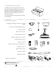
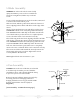
1. Unpacking Your Fan. Carefully open the packaging. Remove items from Styrofoam inserts. Remove motor housing and place on carpet or Styrofoam to avoid damage to finish. Do not discard fan carton or Styrofoam inserts should this fan need to be returned for repairs. Check against parts inventory that all parts have been included. 2. Parts Inventory. a. hanging bracket (pre-attached to canopy). 1 piece a c b b. downrod and hanging ball. 1 piece c. canopy. 1 piece d e d. yoke cover. 1 piece e.
3. Installation Preparation. To prevent personal injury and damage, ensure that the hanging location allows the blades a clearance of 10ft. (3.05m) from the floor and 30in. (76cm) from any wall or obstruction. This fan is suitable for room sizes up to 400 square feet (37.2 square meters). 12ft. - 20ft. (3.66 m - 6.1m) blade edge 30 10 inches feet (76cm) (3.05m) 12ft. - 20ft. (3.66m - 6.1m) downrod installation This fan can be mounted with a downrod on a regular (no-slope) or vaulted ceiling.
. Blade Assembly. WARNING: To reduce the risk of serious bodily injury, DO NOT use power tools to assemble the blades. If overtightened, blades may crack and break. Locate 9 blade attachment screws,9 lock washers,9 nuts,and 3 rubber washers in hardware pack. Slide one blade with the pointed side under the bottom of motor, aligning holes in blade with holes on the edge of the motor.
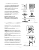
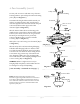
. Fan Assembly. (cont.) safety cable electrical wiring Loosen yoke set screws and nuts at top of motor housing. Remove pin and clip from motor housing yoke. [Refer to diagram 2.] downrod Determine the length of threaded downrod you wish to use. Thread safety cable and electrical wires through threaded end of downrod and pull extra wire slack from the upper end of the downrod. [Refer to diagram 2.
wood ceiling joist 6. Fan Assembly. (cont.) safety cable loop With the hanging bracket secured to the outlet box and able to support the fan, you are now ready to hang your fan. Grab the fan firmly with two hands. Slide downrod through opening in hanging bracket and let hanging ball rest on the hanging bracket. Turn the hanging ball slot until it lines up with the hanging bracket tab.
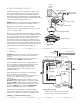
7. Wiring. (cont.) outlet box PLEASE NOTE: Wall and/or remote conrol must be used for fan to operate. If you do not wish to use the wall control, please proceed to Section 8 to continue with fan installation. 3 4 WARNING: CONNECT WIRES IN THE FOLLOWING ORDER ONLY! Connect GREEN ground wire to ground from house or directly to one of the screws from the outlet box. Connect one BLACK wire from wall control to BLACK (hot) lead wire from house.
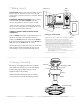
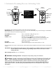
. Automated Learning Process./Activating Code. REMOTE CONTROL LED LIGHT WALL CONTROL LED LIGHT FAN OFF 4 3 FAN SPEED REVERSE LEARN 5 2 1 6 IMPORTANT: Remote and wall controls must be S NC R ONI E with fan in order to properly function. FAN OFF 3 4 2 5 1 FAN SPEED 6 REVERSE LEARN 12V 12V ON/OFF SLIDER SWITCH Install battery (provided) in transmitter and wall control (if applicable). IMPORTANT: Store the transmitter away from excess heat or humidity.
. Testing Your Fan. It is recommended that you test fan before finalizing installation. Test wall control (optional installation) by locating ON/OFF slider switch on wall control, then set to ON position. Test fan speeds. Next, locate remote control. Test fan speed with different fan speed buttons (1 - 6). If the remote control operates the functions of the fan, battery has been installed correctly.
Troubleshooting. WARNING: Failure to disconnect power supply prior to troubleshooting any wiring issues may result in serious injury. Problem: Fan fails to operate. Solutions: 1. Check wall switch to fan/wall control. 2. Check to be sure wall control (optional use) is wired properly. 3. Check to be sure fan is wired properly. 4. Learning process between fan, remote control and, if applicable, wall control may not have been successful and code was not activated.
Caution: This device complies with Part 15 of the FCC rules and Industry Canada license‐exempt RSS standard(s). Operation is subject to the following two conditions: (1) this device may not cause harmful interference, and (2) this device must accept any interference received, including interference that may cause undesired operation. The manufacturer is not responsible for any radio or TV interference caused by unauthorized modifications or change to this equipment.