
Installation Instruction


Installation
cVEND plug
FEIG ELECTRONIC GmbH
Page 8 of 24
cVEND plug - User manual.docx
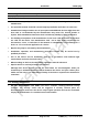
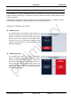
The cVEND plug front consists of a silicon rubber mat (1) with integrated sealing (2) and a fixed
poly carbonate plastic dome (3) which shows the back-lit contactless symbol.
Fig. 4: Plug front with sealing (red colored)
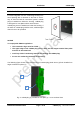
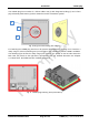
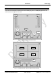
For fastening the cVEND plug front has to be pressed tight against the housing front. Therefore a
clamp range of 2,5 mm (fastening area) on all sides of the cVEND plug antenna PCB is available.
The following figure shows the clamp range (red marked). The picture on the left side shows the
back view, the picture on the right side is perspective view. For detailed dimension see Chapter
3.1. Dimensions. 3D STEP Data are available on request.
Fig. 5: cVEND plug fastening area (red marked)
1
3
2