
User's Manual


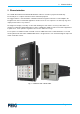
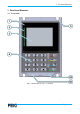
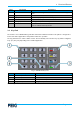
Table Of Contents
- Annex no. 5 (Functional Description - User Manual).pdf
- M90113-10e-PY-B.pdf
- 1 Warnings – Read Before Start-Up!
- 2 Characterization
- 3 Functional Elements
- 4 Mechanical Integration
- 5 Connectors
- 5.1 Connector X1 – Power Supply and MDB Interface
- 5.2 Standby Mode / Wake-Up
- 5.3 Connector X2 – USB Device Interface
- 5.4 Connector X3 – COM 0 (RS232 V.24 Interface)
- 5.5 Connector X4 – USB Host 2 Interface
- 5.6 Connector X5 – Ethernet Interface
- 5.7 Connector X6 - Auxiliary
- 5.8 Connector X7 – USB Host 1
- 5.9 Connector X8 – cVEND SHCR
- 5.10 Connector X9 – COM 2 (RS232 V.24)
- 5.11 SAM Sockets (S1, S2)
- 6 Installation and Setup
- 7 Maintenance and Cleaning
- 8 User Interface
- 9 Technical Data

3 Functional Elements
Page 8 of 38
Label
Description
Intended Use
1
Contactless Reader Antenna
Area for data exchange between cVEND PIN and a contactless payment
card
2
4x green LED
Indicators to show the transaction progress
3
Display
Graphical display to guide the user during operations
4
PIN Pad
Keys to control the operation and to enter a PIN
5
Sealing Lip – all around
Sealing lip that prevents entering of water and dust in the machine
S1, S2
Removal Protection Switches
Switches which must be activated by the installation of cVEND PIN in
order to enable the PIN entry function
Table 1: Front side elements
3.2 Key Pad
The stainless steel cVEND PIN key pad with clear tactile feedback and embossed symbols is designed for
indoor and outdoor applications and provides barrier-free operation.
The key pad function is under software control. The functionality of the function keys (2) and the navigation
keys (4, 5) may vary depending on the installed application.
Fig. 3: cVEND PIN Key Pad
Label
Description
Indicated Use
1
Numeric Keys 0–9
To enter a PIN or other numeric data
2
Function Keys (STOP, CORR, INFO)
To control and modify the entered data
3
OK
OK key with wake-up function (see 5.2)
4, 5
Navigation Keys
Navigation keys
Table 2: Key Pad Elements