Annex no. 5 User Manual Date: 2012-06-11 m. dudde hochfrequenz-technik Vers. no. 1.
INTEGRATION ID ISC.MRMU102-A Module Version final – public (B) 2012-12-03 – Integration Manual M21112-1e-ID-B.
OBID i-scan ® UHF Integration ID ISC.MRMU102-A Note Copyright 2012 by FEIG ELECTRONIC GmbH Lange Strasse 4 D-35781 Weilburg Tel.: +49 6471 3109-0 http://www.feig.de With the edition of this document, all previous editions become void. Indications made in this manual may be changed without previous notice. Copying of this document, and giving it to others and the use or communication of the contents thereof are forbidden without express authority. Offenders are liable to the payment of damages.
OBID i-scan ® UHF Integration ID ISC.MRMU102-A General information's regarding this document • The sign "" indicates extensions or changes of this manual compared with the former issue. • If bits within one byte are filled with "-", these bit spaces are reserved for future extensions or for internal testing- and manufacturing-functions. These bit spaces must not be changed, as this may cause faulty operation of the reader. • The following figure formats are used: 0...9: 0x00...0xFF: b0...
OBID i-scan ® UHF Integration ID ISC.MRMU102-A Contents 1. Safety Instructions / Warning - Read before start-up ! 5 2. Performance Features of the Reader 6 2.1. Available Reader Types .................................................................................................... 6 2.2. Optional Accessories ........................................................................................................ 6 3. Assembly and Wiring 7 3.1. Module Versions ....................................
OBID i-scan ® UHF Integration ID ISC.MRMU102-A 1. Safety Instructions / Warning - Read before start-up ! • The device may only be used for the intended purpose designed by for the manufacturer. • The operation manual should be conveniently kept available at all times for each user. • Unauthorized changes and the use of spare parts and additional devices which have not been sold or recommended by the manufacturer may cause fire, electric shocks or injuries.
OBID i-scan ® UHF Integration ID ISC.MRMU102-A 2. Performance Features of the Reader The Reader ID ISC.MRMU102 is designed for reading of passive data carriers, so-called „Smart Labels“ at an operating frequency in the UHF band between 860 MHz and 960 MHz. Transponders according to EPC Class1 Gen2 are supported. Optional an Upgrade Code for the reading of ISO 18000-6-C transponders is available. The reader is designed for application with small tag population.
OBID i-scan ® UHF Integration ID ISC.MRMU102-A 3. Assembly and Wiring 3.1. Module Versions This reader version has been designed for mounting in other equipment. NOTE: Before any installation the intended position of the reader should be tested for its suitability. 3.1.1.
OBID i-scan ® UHF Integration ID ISC.MRMU102-A 4. Connections The module version of the reader is equipped with an asynchronous RS232 Interface (X2) and a USB Interface (X3). The Table 2: Connectors shows which connector can be used for the different interface cable. Table 2: Connectors Connector ANT 1-3 ANT 4 Description External Antenna ANT 1 - 3 Internal Antenna ANT 4 X1 Power Supply via Connector X1 X2 RS232 Interface on Connector X2 X3 USB Interface on Connector X3 4.1. Antenna Terminals 4.
OBID i-scan ® UHF FEIG ELECTRONIC GmbH Integration Page 9 of 21 ID ISC.MRMU102-A Integration Manual M21112-1eID-B.
OBID i-scan ® UHF Integration ID ISC.MRMU102-A 4.1.2. Internal Antenna ANT 4 Additionally the reader is equipped with an internal antenna (ANT4). The internal antenna supports far field transponders as well as near field transponders. The internal antenna is located in the bottom left corner of the housing and is marked with an antenna symbol. The maximum read range of the antenna in combination with a far field transponder is approx. 40 cm.
OBID i-scan ® UHF Integration ID ISC.MRMU102-A 4.3. RS232 Interface on Connector X2 For the connection of the asynchronous interface RS232 the reader provides a 9-pin DSubminiature female connector. (See also Connections). Table 5: Connection assignment of the connector X2 X2 Interface 2 TxD 3 RxD 5 GND 7 GND 1;4;6;8;9 n.c. For this reader a serial cable is available. Table 6: Serial Data Cable Feig Part No. Description 1690.000.00 ID CAB.
OBID i-scan ® UHF Integration ID ISC.MRMU102-A 4.2. USB Interface on Connector X3 There is a USB-socket X3 on board for the connection of the USB-Interface. The pinout is standardized. The data rate is reduced to 12 Mbit (USB full speed). A standard USB-cable can be used. Figure 3: USB interface for host communication NOTE: The length of the USB-cable can be a max. of 5 meter.
OBID i-scan ® UHF Integration ID ISC.MRMU102-A 6. Technical Data MECHANICAL DATA Housing - Dimension (W x H x D) 137 mm x 77 mm x 17 mm Weight 60 g Protection Class - Colour - ELECTRICAL DATA Power Supply 12 V DC – 24 V DC Power Consumption max. 7 W Operating Frequency 860 MHz to 960 MHz RF-Power max.
OBID i-scan ® UHF Further Features Integration ID ISC.MRMU102-A Anticollision (max.
OBID i-scan ® UHF Integration ID ISC.MRMU102-A * Caution: Overheating of the device may result in performance losses. It is recommended to activate the RF of the reader only if there is a transponder in the detection range of an antenna. FEIG ELECTRONIC GmbH Page 15 of 21 Integration Manual M21112-1eID-B.
OBID i-scan ® UHF Integration ID ISC.MRMU102-A 7. Radio Approvals 7.1. Europe (CE) When used according to regulation, this radio equipment conforms with the basic requirements of Article 3 and the other relevant provisions of the R&TTE Guideline 1999/E6 dated March 99. Equipment Classification according to ETSI EN 301 489: Class 2 FEIG ELECTRONIC GmbH Page 16 of 21 Integration Manual M21112-1eID-B.
OBID i-scan ® UHF Integration ID ISC.MRMU102-A 7.2. Declaration of Conformity FEIG ELECTRONIC GmbH Page 17 of 21 Integration Manual M21112-1eID-B.
OBID i-scan ® UHF FEIG ELECTRONIC GmbH Integration Page 18 of 21 ID ISC.MRMU102-A Integration Manual M21112-1eID-B.
OBID i-scan ® UHF Integration ID ISC.MRMU102-A 7.3. USA (FCC) and Canada (IC) 7.3.1. USA (FCC) and Canada (IC) warning notices Product name: ID ISC.MRMU102-A Reader name: ID ISC.MRMU102-A FCC ID: IC: Notice for USA and Canada PJMMRU102 6633A-MRM102 This device complies with Part 15 of the FCC Rules and with RSS-210 of Industry Canada. Operation is subject to the following two conditions.
OBID i-scan ® UHF Integration ID ISC.MRMU102-A 7.3.2. Label Information Reader Module ID ISC.MRMU102-A The following information has to be mounted outside on the housing of the reader module. 7.3.3.
OBID i-scan ® UHF Integration ID ISC.MRMU102-A ANNEX A - Accessories The following accessories are available for the Reader. Article No. Part No. Description ID NET.12V-B-EU Power Supply 95 - 265V AC Input Voltage, (Continental European Plug), with angular DC Plug 2,5mm*5,5mm Output: 12 V DC/ ; 700mA Ambient Operating Temperature: 0°C to +40°C ID NET.
MONTAGE INSTALLATION ID ISC.MRU102-PoE ID ISC.MRU102-USB Gehäuse-Variante Housed Version preliminary public (B) 2012-03-22 M20110-1de-ID-B.
DEUTSCH Montage / Installation Deutsche Version ab Seite 3 ENGLISH OBID i-scan® English version from page 23 FEIG ELECTRONIC GmbH Seite 2 von 42 ID ISC.MRU102 M20110-1de-ID-B.
OBID i-scan® Montage / Installation ID ISC.MRU102 Hinweis Copyright 2012 by FEIG ELECTRONIC GmbH Lange Straße 4 D-35781 Weilburg Tel.: +49 6471 3109-0 http://www.feig.de Alle früheren Ausgaben verlieren mit dieser Ausgabe ihre Gültigkeit. Die Angaben in diesem Dokument können ohne vorherige Ankündigung geändert werden. Weitergabe sowie Vervielfältigung dieses Dokuments, Verwertung und Mitteilung ihres Inhalts sind nicht gestattet, soweit nicht ausdrücklich zugestanden.
OBID i-scan® Montage / Installation ID ISC.MRU102 Inhalt 1 Sicherheits- und Warnhinweise - vor Inbetriebnahme unbedingt lesen 6 2 Leistungsmerkmale der Readerfamilie ID ISC.MRU102 7 3 4 5 2.1 Verfügbare Readertypen ............................................................................................ 7 2.2 Verfügbares Zubehör.................................................................................................. 7 Montage 8 3.1 Gehäusevariante .............................
OBID i-scan® 8 Montage / Installation Anhang 8.1 8.1.1 ID ISC.MRU102 20 Zubehör ..................................................................................................................... 20 Wandmontagesatz ID ISC.MS.MR/PR-A ................................................................ 21 FEIG ELECTRONIC GmbH Seite 5 von 42 M20110-1de-ID-B.
OBID i-scan® Montage / Installation ID ISC.MRU102 1 Sicherheits- und Warnhinweise - vor Inbetriebnahme unbedingt lesen • Das Gerät darf nur für den vom Hersteller vorgesehenen Zweck verwendet werden. • Die Bedienungsanleitung ist zugriffsfähig aufzubewahren und jedem Benutzer auszuhändigen.
OBID i-scan® 2 Montage / Installation ID ISC.MRU102 Leistungsmerkmale der Readerfamilie ID ISC.MRU102 Der Reader ist für das Lesen von passiven Datenträgern, sogenannten „Smart Labels“, mit einer Betriebsfrequenz im UHF Bereich zwischen 860 MHz und 960 MHz entwickelt. Es werden Transponder nach EPC Class1 Gen2 unterstützt. Optional kann eine Freischaltung zum Lesen von Transpondern nach ISO 18000-6-C erfolgen. Der Leser ist konzipiert für Anwendungen mit geringer Transponderdichte.
OBID i-scan® 3 Montage / Installation ID ISC.MRU102 Montage 3.1 Gehäusevariante Der Reader ist für Anwendungen im Innenbereich konzipiert. Eine Wandmontage ist mit dem optional erhältlichen Wandmontagesatz möglich. (Siehe Anhang Wandmontagesatz ID ISC.MS.MR/PR-A) Hinweise: • Vor der endgültigen Installation sollte der geplante Installationsort auf seine Tauglichkeit geprüft werden. 3.
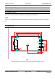
OBID i-scan® 4 Montage / Installation ID ISC.MRU102 Anschlüsse Je nach Variante des Readers stehen unterschiedliche Anschlussklemmen zur Verfügung. Abbildung 3: Anschlussübersicht zeigt die Anordnung und in Tabelle 2: Anschlussklemmen ist dargestellt, welche Anschlüsse für die einzelnen Schnittstellenkabel verwendet werden sollen.
OBID i-scan® 4.1 Montage / Installation ID ISC.MRU102 Antennenanschluss ANT 1 Zum Anschluss der externen Antenne befindet sich auf der Leiterplatte eine SMA-Buchse (ANT1). Das maximale Anzugsdrehmoment der SMA-Buchsen beträgt 0,45 Nm. Achtung: • Höhere Anzugsdrehmomente führen zur Zerstörung des Steckers. Klemme ANT 1 Beschreibung Anschluss der externen Antenne (Eingangsimpedanz 50 Ω) Tabelle 3: Anschluss der externen Antenne Hinweise: • 4.
OBID i-scan® Montage / Installation ID ISC.MRU102 4.3 Versorgungsspannung 4.3.1 Spannungsversorgung über X1 Die Versorgungsspannung von 12 - 24 V DC ist an der Buchse X1 der Leiterplatte anzuschließen. Buchse Kurzzeichen Beschreibung X1 / Innen Vcc Vcc – Versorgungsspannung (+) X1 / Außen GND Ground – Versorgungsspannung (-) X1 Tabelle 4: Anschluss der Versorgungsspannung Hinweis: • Eine Verpolung der Versorgungsspannung kann zur Zerstörung des Gerätes führen.
OBID i-scan® Montage / Installation ID ISC.MRU102 4.3.2 Versorgungsspannung über PoE (Power over Ethernet) (ID ISC.MRU102-PoE) Alternativ kann die PoE Variante über den LAN-Anschluss X4 mit Hilfe eines „Power over Ethernet“-Netzteil gem. IEEE802.3af*, Class2 (6,49 Watt) versorgt werden. Die DC Speisung kann über die freien Pin’s 4,5 und 7,8 erfolgen (Midspan-Power), als auch eine „Phantomspeisung“ über die Signalverbindung 1,2,3 und 6 ist möglich (Inline-Power).
OBID i-scan® Montage / Installation ID ISC.MRU102 4.4 Ethernet-Schnittstelle an X2 (10/100Tbase) Der Reader verfügt über eine integrierte 10/100 base-T Netzwerkschnittstelle mit Standard RJ-45Anschluss. Der Anschluss erfolgt über X2 und hat eine automatische „Crossover Detection“ entsprechend dem 1000BASE-T Standard. Bei einer strukturierten Verkabelung sollten mindestens Kabel der Kategorie CAT5 verwendet werden. Dies garantiert einen problemlosen Betrieb bei 10 Mbps oder 100 Mbps.
OBID i-scan® Montage / Installation ID ISC.MRU102 4.5 USB – Schnittstelle X3 (Host Kommunikation) Der Anschluss der USB-Schnittstelle erfolgt über die Buchse X3. Die Belegung ist genormt. Die Daten-rate des Readers ist auf 12 Mbit beschränkt (USB Full Speed). Es kann ein Standard-USBKabel verwendet werden. Abbildung 5: USB-Schnittstelle für Host Kommunikation Hinweis: • Die maximale Länge des USB-Kabels darf 5 m betragen. Längere Kabel sind nicht erlaubt.
OBID i-scan® 5 Montage / Installation ID ISC.MRU102 Bedien und Anzeigeelemente 5.1 LED Die LED des Readers kann per Software konfiguriert werden. Die folgende Tabelle 8 zeigt die Werkseinstellung. Kurzzeichen LED grün Beschreibung "RUN " - Leuchtet, wenn der Reader betriebsbereit ist. „TRANSPONDER“ LED rot - Leuchtet, wenn ein Transponder erkannt wird.
OBID i-scan® 6 Montage / Installation ID ISC.MRU102 Technische Daten Mechanische Daten • Gehäuse Kunststoff ABS geschlossen • Abmessungen ( B x H x T ) 145 mm x 85 mm x 27 mm • Gewicht 200 g • Schutzart IP 30 • Farbe ähnlich RAL 9018 (Papyrusweiß) Elektrische Daten • Spannungsversorgung – ID ISC.MRU102-USB – ID ISC.MRU102-PoE 12 V DC bis 24 V DC 12 V DC bis 24 V DC oder PoE • Leistungsaufnahme max. 7 W • Betriebsfrequenz 860 MHz bis 960 MHz • Sendeleistung max.
OBID i-scan® Montage / Installation ID ISC.
OBID i-scan® 7 Montage / Installation ID ISC.MRU102 Funk Zulassungen 7.1 Europa (CE) Die Funkanlage entspricht, bei bestimmungsgemäßer Verwendung den grundlegenden Anforderungen des Artikels 3 und den übrigen einschlägigen Bestimmungen der R&TTE Richtlinie 1999/5/EG vom März 1999. Equipment Classification gemäß ETSI EN 301 489: Class 2 FEIG ELECTRONIC GmbH Seite 18 von 42 M20110-1de-ID-B.
OBID i-scan® Montage / Installation ID ISC.MRU102 7.2 Declaration of Conformity FEIG ELECTRONIC GmbH Seite 19 von 42 M20110-1de-ID-B.
OBID i-scan® 8 Montage / Installation ID ISC.MRU102 Anhang 8.1 Zubehör Zu dem Reader ist folgendes Zubehör zu erhalten. Artikel Nr. 1688.002.00 3886.000.00 3887.000.00 Bezeichnung Beschreibung ID NET.12V-B-EU Netzteil 95 - 265V AC Eingangsspannung, (Continental European Plug), mit abgewinkelten DC Stecker 2,5mm*5,5mm ; 700mA Output: 12 V DC/ Umgebungstemperatur: 0°C bis +40°C ID NET.
OBID i-scan® Montage / Installation ID ISC.MRU102 8.1.1 Wandmontagesatz ID ISC.MS.MR/PR-A Mit Hilfe des Wandmontagesatzes kann der Reader auf einer ebenen Fläche befestigt werden. • Die Schrauben auf der Rückseite des Readers entfernen. • Die einzelnen Wandhalter mit denen im Montagesatz beigefügten Schrauben befestigen. Abbildung 6: Montage Wandhalter 125 65 93 153 Abbildung 7: Montage - Bohrmaße (alle Maße in mm) FEIG ELECTRONIC GmbH Seite 21 von 42 M20110-1de-ID-B.
OBID i-scan® FEIG ELECTRONIC GmbH Montage / Installation Seite 22 von 42 ID ISC.MRU102 M20110-1de-ID-B.
OBID i-scan® Montage / Installation ID ISC.MRU102 Note Copyright 2012 by FEIG ELECTRONIC GmbH Lange Strasse 4 D-35781 Weilburg Tel.: +49 6471 3109-0 http://www.feig.de With the edition of this document, all previous editions become void. Indications made in this manual may be changed without previous notice. Copying of this document, and giving it to others and the use or communication of the contents thereof are forbidden without express authority. Offenders are liable to the payment of damages.
OBID i-scan® Montage / Installation ID ISC.MRU102 Contents 9 Safety Instructions / Warning - Read before start-up ! 26 10 Performance Features of the readers 27 11 10.1 Available Reader types ............................................................................................. 27 10.2 Optional accessories ................................................................................................ 27 Assembly and Wiring 11.1 Housed versions .........................................
OBID i-scan® 16 Montage / Installation Annex 16.1 ID ISC.MRU102 41 Accessories .............................................................................................................. 41 16.1.1 Wall mounting kit ID ISC.MS.MR/PR-A .................................................................. 42 FEIG ELECTRONIC GmbH Seite 25 von 42 M20110-1de-ID-B.
OBID i-scan® 9 Montage / Installation ID ISC.MRU102 Safety Instructions / Warning - Read before start-up ! • The device may only be used for the purpose intended by the manufacturer. • The operation manual should be kept readily available at all times for each user. • Unauthorized changes and the use of spare parts and additional devices which have not been sold or recommended by the manufacturer may cause fire, electric shocks or injuries.
OBID i-scan® 10 Montage / Installation ID ISC.MRU102 Performance Features of the readers The Reader ID ISC.MRU102 is designed for reading of passive data carriers, so-called „Smart Labels“ at an operating frequency in the UHF band between 860 MHz and 960 MHz. Transponders according to EPC Class1 Gen2 are supported. Optional an Upgrade Code for the reading of ISO 18000-6-C transponders is available. The reader is designed for application with small tag population.
OBID i-scan® 11 Montage / Installation ID ISC.MRU102 Assembly and Wiring 11.1 Housed versions The Reader is designed for an office environment. It can be wall-mounted, in this case the wallmount kit should be ordered separately. (see Appendix: Wall mounting kit ID ISC.MS.MR/PR-A) Notes: • Before any installation the intended position of the reader should be tested for its suitability. 11.1.
OBID i-scan® 12 Montage / Installation ID ISC.MRU102 Connections Depending on the reader variant different connectors are available. Figure 3: Connection overview displays the arrangement and the Table 2: Connectors shows which connector can be used for the different interface cable.
OBID i-scan® Montage / Installation ID ISC.MRU102 12.1 Antenna Terminal ANT 1 A SMA socket (ANT1) is provided on the circuit board for connecting the external antenna. The maximum tightening torque for the SMA socket is 0.45 Nm. Caution: • Higher tightening torque will damage the connector.
OBID i-scan® Montage / Installation ID ISC.MRU102 12.3 Power supply 12.3.1 Power supply via X1 Connect the 12 - 24 V DC/ supply voltage to socket X1 on the circuit board. Terminal Name Description X1 / inside Vcc Vcc – supply voltage (+) X1 / outside GND Ground – supply voltage (-) X1 Table 4: Connecting the supply voltage Note: • Reversing the polarity of the supply voltage may destroy the device.
OBID i-scan® Montage / Installation ID ISC.MRU102 12.3.2 Power supply via PoE (Power over Ethernet) on X4 (ID ISC.MRU102-PoE) Optional the reader (only MRU102-PoE) can be powered via the LAN connector on X4 with the use of a PoE „Power over Ethernet“ power supply according to IEEE802.3af*, Class2 (6,49 Watt). The DC supply can be achieved via the free pin’s 4,5 and 7,8 (Midspan-Power). Also a “Phantom Powering” (Inline-Power) via the signal pin’s 1,2,3,and 6 is possible.
OBID i-scan® Montage / Installation ID ISC.MRU102 12.4 Ethernet-Interface on X4 (10/100Tbase) The Reader has an integrated 10 / 100 base-T network port for an RJ-45. Connection is made on X4 and has an automatic “Crossover Detection” according to the 100BASE-T Standard. With structured cabling CAT 5 cables should be used. This ensures a reliable operation at 10 Mbps or 100 Mbps. The prerequisite for using TCP/IP protocol is that each device has a unique address on the network.
OBID i-scan® Montage / Installation ID ISC.MRU102 12.5 USB – Interface X3 (Host communication) There is a USB-socket X3 on board for the connection of the USB-Interface. The pinout is standardized. The data rate is reduced to 12 Mbit (USB full speed). A standard USB-cable can be used. Figure 5: USB interface for host communication Note: • The length of the USB-cable can be a max. of 5 meter.
OBID i-scan® 13 Montage / Installation ID ISC.MRU102 Control and display elements LED 13.1 LED The Reader’s LED can be configured through software. The following Table 8 shows the default setting. Abbreviation LED green Description "RUN " - Turns on when the Reader is ready „LABEL“ LED red LED orange - Turns on when a transponder is detected.
OBID i-scan® 14 Montage / Installation ID ISC.MRU102 Technical Data Mechanical Data • Housing ABS plastic, enclosed • Dimensions (W x H x D) 145 mm x 85 mm x 27 mm • Weight 200 g • Degree of Protection IP 30 • Color similar RAL 9018 (papyrus white) Electrical Data • Supply voltage – ID ISC.MRU102-USB – ID ISC.MRU102-PoE 12 V DC to 24V DC 12 V DC to 24V DC or PoE • Power consumption max. 7 W • Operating frequency 860 MHz to 960 MHz • Transmitting power max.
OBID i-scan® Montage / Installation ID ISC.MRU102 Ambient Conditions • • Temperature range - Operation - Storage -25 °C to +55 °C (-USB) -25 °C to +45 °C (-PoE) -25 °C to +85 °C Humidity 5 % to 95 % non condensing Applicable Norms • Radio approval - Europe - USA - Canada EN 302 208 FCC 47 CFR Part 15 IC RSS-GEN, RSS-210 • EMC EN 301 489 • Vibration EN 60068-2-6 10 Hz to 150 Hz : 0,075 mm / 1 g • Shock EN 60068-2-27 Acceleration FEIG ELECTRONIC GmbH Seite 37 von 42 : 30 g M20110-1de-ID-B.
OBID i-scan® Montage / Installation ID ISC.MRU102 15 Radio Approvals 15.1 Europe (CE) When used according to regulation, this radio equipment conforms with the basic requirements of Article 3 and the other relevant provisions of the R&TTE Guideline 1999/E6 dated March 99. Equipment Classification according to ETSI EN 301 489: Class 2 FEIG ELECTRONIC GmbH Seite 38 von 42 M20110-1de-ID-B.
OBID i-scan® Montage / Installation ID ISC.MRU102 15.2. USA (FCC) and Canada (IC) 15.2.1 USA (FCC) and Canada (IC) warning notices Product name: ID ISC.MRU102-USB ID ISC.MRU102-PoE Reader name: ID ISC.MRU102-USB ID ISC.MRU102-PoE FCC ID : Notice for USA and IC Canada : PJMMRU102 6633A-MRM102 This device complies with Part 15 of the FCC Rules and with RSS-210 of Industry Canada. Operation is subject to the following two conditions.
OBID i-scan® Montage / Installation ID ISC.MRU102 15.2.2 Label Information Reader Module ID ISC.MRMU102-A The following information has to be mounted outside on the housing of the reader module. 15.2.
OBID i-scan® 16 Montage / Installation ID ISC.MRU102 Annex 16.1 Accessories The following accessories are available for the Reader. Article No. 1688.002.00 3886.000.00 3887.000.00 Part No. Description ID NET.12V-B-EU Power Supply 95 - 265V AC Input Voltage, (Continental European Plug), with angular DC Plug 2,5mm*5,5mm ; 700mA Output: 12 V DC/ Ambient Operating Temperature: 0°C to +40°C ID NET.
OBID i-scan® Montage / Installation ID ISC.MRU102 16.1.1 Wall mounting kit ID ISC.MS.MR/PR-A The wall mounting kit can be used to attach the Reader to a flat surface. • Remove the screws from the back side of the Reader. • Attach the individual wall hangers using the screws supplied with the mounting kit. Figure 6: Mounting wall hangers 125 65 93 153 Figure 7: Mounting drill dimensioning (all dimensions in mm) FEIG ELECTRONIC GmbH Seite 42 von 42 M20110-1de-ID-B.