
Installation Guide

(E) 3/05
MURRAY FEISS
© MURRAY FEISS IMPORT LLC.
ASSEMBLY INSTRUCTIONS FOR OL3411
Machine Screw
Small Hex Nut
Fixture Plate
Ball Cap Nut
Canopy Loop
Adjustable
Chain Link
Adjustable
Chain Link
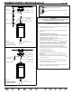
Fig. 1
CHAIN HUNG
INSTALLATION
Fig. 2
FLUSH MOUNT
INSTALLATION
Chain
Mounting Plate
Fixture Wires &
Ground Wire
Fixture Loop
Rubber Washer
Bulb
(not included)
Canopy
Threaded Pipe
Canopy
Loop
Fixture Wire &
Ground Wire
Ball Cap Nuts
Hex Nut &
Lock Washer
Mounting Plate
Machine Screw
Bulb
(not included)
Fixture Plate
Threaded Pipe
IMPOR
T
ANT
TURN OFF
POWER A
T
MAIN FUSE OR CIRCUIT
BREAKER
BOX BEFORE ST
AR
TING INS
T
ALLA
TION
Car
efully unpack and identify all parts befor
e beginn
ing
assembly
. Bulb not included.
1. Install light bulb (not include
d). Se
e relam
ping label at socket area for
type and maximum allowed wattage.
2.
This fixture can be mounted onto ceiling either as chain hung or
flush mount:
CHAIN HUNG INST
ALLA
TION- Fig. 1:
A.
Take fixture wire (with plastic insulation) and ground wi
re and
thread through rubber washer and fixture loop.
Then install loop
onto threaded pipe located at top of lantern.
B. Determine the desired lengt
h
of chain to ha
ng
. Rem
ove any
unwanted links with chain pliers
.
C.
This fixture is supplied with 2 adjustable cha
in li
nks.
These
links
are opened and closed by twisting cylinder on chain link. One
threaded chain link should be installed onto Fixture loop and the
other should be installed onto canopy loop.
The sta
ndard c
hain
sho
uld be i
nstal
led in between these 2 threaded chain links.
D.
T
ake gro
und
wire
and wea
ve
through a
bove
cha
in links,
the
n
thread through c
ent
e
r
hol
e i
n c
anopy l
oop. Re
pea
t
w
i
th fi
xt
u
re
w
i
re
(wire wit
h pla
sti
c i
nsulation).
FLUSH I
N
ST
ALL
A
TION
- Fig. 2:
A. Remove
and di
scard c
anopy l
oop a
nd thre
a
ded pi
pe
from
fixture pla
te
.
B. Slip fi
xture
pl
at
e
, loc
k wash
er
, and he
x nut
t
hrough fixt
ure
w
i
res
and ground wire
.
T
hen i
nsta
ll
t
hem
onto t
hrea
de
d pipe
by fa
s
t
eni
ng
secure
ly wit
h he
x nu
t
.
3. Cut
exc
ess wires
le
a
ving onl
y 6" (15cm
) le
ngt
h of w
i
res above
fixt
ure pl
a
te
. Spli
t fi
xt
ure w
i
re i
nt
o two s
t
rands.
T
hen stri
p of
f
3/4" (19m
m) of out
er plastic
insula
t
ion.
4.
Follow enc
losed “
Fixt
ure Ins
t
al
l
at
i
on Ins
t
ruct
i
ons
”
for el
e
ct
rical
and fixture i
ns
t
al
l
at
i
on
ont
o ce
i
li
ng out
le
t
box.
Fig. 3
Twist to open or close chain link.
Threaded Chain Link