
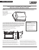
Installation Sheet

FEIT ELECTRIC COMPANY | PICO RIVERA, CA | (800) 543-3348 | FAX (562) 908-6360 | www.feit.com
Wall Mount Installation
J-Box Mount Mount Installation
MODEL S15CWPK/850/BZ
WARNING: TURN OFF THE MAIN POWER AT THE CIRCUIT BREAKER BEFORE
INSTALLING THE FIXTURE IN ORDER TO PREVENT POSSIBLE ELECTRIC SHOCK.
INSTALLATION OPTIONS
This LED Wall-Packs light uses the latest in solid state lighting technology for long life, low maintenance and high efficiency.
Note:
Fig A.
screws
Fig D.
back
plate
front
cover
front
cover
screws
Fig H.
back
plate
front
cover
screws
The same as traditional HID lighting, it could be mounted a standard photocell on the enclosure, to make it completely suitable for street lighting.
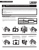
1. Open and remove the front cover from the back plate
by using a phillip screwdriver to remove the screws (Fig A).
1. Open and remove the front cover
from the back plate by using a
phillip screwdriver to remove the
screws (Fig E).
2. Drill the 4 (A) holes on the back
plate needed to install on your
J-box. Remove center knockout (C).
Make sure power is off. Feed power
supply wires thru the knockout hole
(Fig. F).
3. Mount the back plate to
the J-box (Fig G) and
connect the wires.
Refer to the circuit
diagram above.
4. Assemble front cover back onto
the back plate. Tighten enclosure
screws to seal fixture.
2. Drill the 3 (B) holes indicated on the back plate (Fig B).
3. Align the back plate on the surface being installed. If anchors
are required, mark the 3 holes to be drilled for wall anchors
(Fig C).
5. Assemble front cover back onto the back plate. Tighten the enclosure
screws to seal fixture (Fig D).
4. Make sure power is off from the circuit breaker or fuse. Feed the power supply
wires through the conduit inlet desired on the back plate. Connect the wires.
Refer to the circuit diagram below:
An internal power-factor-corrected switch-mode supply allows it to be used from any nominal 100V-277V, 60Hz AC supply without any variation
in light output.
Suitable for use in the following locations:
• Ambient Temp: -40~+40°C
• Wet Locations
Fig B.
5.72”
B
B
6.59”
back
plate
Supply Line (Black)
Supply Neutral (White)
Supply Grounding (Green)
Box Grounding (Green)
Neutral (White)
Line (Black)
LED DRIVER
Twist-on wire connector
check whether wires are connected correctly.
Factory Wired
LED to Driver
Fig C.
Check whether the lighting
fixture is firmly fixed.
Check whether the lighting
fixture is firmly fixed.
back
plate
Fig E.
screws
front
cover
back
plate
back
plate
Fig F.
A
C
Fig G.
CIRCUIT DIAGRAM