December 20, 2010 FEIYU TECH FY-3ZT GCS & AFSS AUTOPILOT SYSTEM INSTALLATION & OPERATION MANUAL
GuiLin FeiYu Electronic Technology Co., Ltd. Dear Pilot, Thank you for purchasing the FY-3ZT Full Function Autopilot with GCS & AFSS from FeiYu Tech. In order to achieve full potential and safe operation of this product, please carefully read this manual prior to installation. Attention: The installation and use of this autopilot require advance skill and knowledge in flying remote controlled fixed wing aircraft, the operations of amateur autopilot system and ground control station (GCS).
GuiLin FeiYu Electronic Technology Co., Ltd. Introduction: What it Does FY-3ZT is an advanced autopilot with patented Attitude Flight Stabilization System AFSS™ that allows you to view and change in real time the flight parameters of your flying aircraft via your Ground Control Station (GCS).
GuiLin FeiYu Electronic Technology Co., Ltd. Major Auto Pilot Components 1. 2. 3. 4. 5. 6. 7. 8. 9. 10. 11. 12. 13. 14. 15. FY-3ZT provides high-precision flight attitude measurement and control through the utilization of an integrated 32 ARM7 microprocessor, GPS receiver, three-axis MEMS gyros, three-axis accelerometer, barometric pressure sensor, attitude algorithm, Kalman filtering and data fusion algorithms. 10Hz data rate GPS receiver, 35 seconds fast positioning time and accuracy of 2.
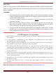
GuiLin FeiYu Electronic Technology Co., Ltd. Technical parameters Table 1: Unless specified, values are at operating temperature of 25 ℃. Component Main Supply Voltage Min Value 4.0 Main Supply Current Altitude Measurement Range GPS Ground Speed Measurement Range GPS Horizontal Navigation accuracy Barometric Pressure Altitude accuracy Standard Value 5 Max Value 6.
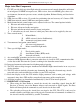
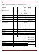
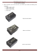
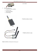
GuiLin FeiYu Electronic Technology Co., Ltd. FY-3ZT INSTALATION 1. Before installation, please check and ensure your FY-3ZT pack contains the following main components: a. Flight controller module b. AHRS & GPS module c. Remote adapter module d. GPS module Flight Controller Module AHRS & GPS Module Remote Adapter Module GuiLin FeiYu Electronic Technology Co., Ltd http://www.feiyudz.cn Page 5 E-mail: service@feiyu-tech.
GuiLin FeiYu Electronic Technology Co., Ltd. GPS Module 2. Optional components: a. OSD Video overlay modules b. Current sensor c. Data radio module d. Other fittings FY-605 Data Radio (433mhz) FY-606 Data Radio (2.4ghz) Note: Data Radio selection please refer page 8. GuiLin FeiYu Electronic Technology Co., Ltd http://www.feiyudz.cn Page 6 E-mail: service@feiyu-tech.
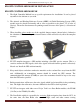
GuiLin FeiYu Electronic Technology Co., Ltd. FLIGHT CONTROLLER MODULE INSTALLATION FLIGHT CONTROLLER MODULE 1. The flight Controller Module has no special requirements for installation. It can be placed anywhere in the airframe as you wish. 2. The Attitude and Heading Reference System (AHRS) & Global Positioning System (GPS) module must be placed horizontally and as close as possible to the plane‘s CG (Center of Gravity). The arrow direction must be pointing towards the nose of the plane (i.e.
GuiLin FeiYu Electronic Technology Co., Ltd. information back to the GCS. The asynchronous serial interface protocol between FY-3ZT autopilot and communications link is RS232-TTL level, the baud rate is 19200. 9. Place the Data Radio module as far as possible away from the GPS module, AHRS, GPS and servos in order to avoid interference to these equipments. The Data Radio antennas should be installed vertically upward or downward. 10.
GuiLin FeiYu Electronic Technology Co., Ltd.
GuiLin FeiYu Electronic Technology Co., Ltd. Baud rate: 19200 Data bits: 8 Stop bits: 1 Parity: None TX1 connected to the RX ‗s data radio RX1 connected to the TX ‗s data radio Connection diagram AHSR&GPS Serial Port 0 Serial Port 1 Data radio + GND Camera Voltage monitoring and Current Sensor device. Servo 1 Servo 2 Power supply Aileron servo Rudder servo Elevator servo Throttle servo FY-3ZT AHRS & GPS Module Interface GuiLin FeiYu Electronic Technology Co., Ltd http://www.feiyudz.
GuiLin FeiYu Electronic Technology Co., Ltd. RX0 TX0 +5V GND RX1 TX1 +5V GND Connect to GPS module Connect to controller module GuiLin FeiYu Electronic Technology Co., Ltd http://www.feiyudz.cn Page 11 E-mail: service@feiyu-tech.
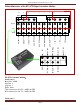
GuiLin FeiYu Electronic Technology Co., Ltd. FY-3ZT Remote Adapter Module Interface GND +5V TX1 RX1 GND +5V TX0 RX0 Signal +5V GND No use CH7_IN CH6_IN CH5_IN RUD_IN THR_IN ELE_IN AIL_IN Not used Functions UART0 UART1 AIL_IN ELE_IN THR_IN RUD_IN CH5_IN CH6_IN CH7_IN Description Data radio module connection Serial port connection to PC Aileron Elevator Throttle Rudder Channel 5 Channel 6 Channel 7 GuiLin FeiYu Electronic Technology Co., Ltd http://www.feiyudz.
GuiLin FeiYu Electronic Technology Co., Ltd.
GuiLin FeiYu Electronic Technology Co., Ltd. FY-3ZT Power Supply 1. To ensure uninterrupted autopilot function, it is critical that your power system outputs a stable and clean 5 volt power source to the FY-3ZT system. 2. To avoid current fluctuations, ideally the power source supply to the servos should be separate from the autopilot. 3. If the power source for the Autopilot system and servos are the same, then we highly recommend a battery or BEC supply with higher than 3 amps output.
GuiLin FeiYu Electronic Technology Co., Ltd. AUTOPILOT CONNECTION OPTIONS There are three options when setting up your FY-3ZT system. Please review them all and choose the one that best suits your needs. Option 1: Ground Station Controlled Flight a) In this option, your aircraft is controlled only by the GCS (Figure 1). With this setup you do not have a RC receiver in the plane (Figure 2).
GuiLin FeiYu Electronic Technology Co., Ltd. to the digital signal conversion and processing, some delay in manual control transmission will occur. Refer page 13 on notes on data transfer frequency (Hz). OPTION 1: ON BOARD AIRCRAFT DIAGRAMME GPS Module AIL Servo ELE Servo THR Servo RUD Servo 5V battery Data Radio OPTION 1: ADVANTAGE Option 1 will make on board installation easier since the RC Receiver does not need to be installed on board. You save on weight and installation area.
GuiLin FeiYu Electronic Technology Co., Ltd. If you choose to use the 5.0 volt power from your ESC BEC, you can plug the throttle control wire directly into the ―THR‖ port. However please ensure that your ESC internal BEC can supply a minimum of 3.0 A current. We highly recommend that you have an external BEC instead. The 5.0 volt External BEC power input is connected to the I/O1 port.
GuiLin FeiYu Electronic Technology Co., Ltd. Data Radio Receiver battery RC Remote Receiver AIL ELE THR RUD CH5 CH6 USB—Serial TTL OPTION 1: Ground Station Requirements: a) You will need at least a 6 channels Receiver b) You will also need at least two, 3-position switches on your Radio Transmitter.
GuiLin FeiYu Electronic Technology Co., Ltd. b) Since both systems can be used to control your aircraft, the maximum flight range is either your RC Transmitter or the Data Radio, whichever can reach further out. c) e.g. If your RC Transmitter is out of range, while Data Radio is still within range, the Data Radio can still fly the plane via the planned GCS flight route. d) In Option 2, you have direct RC Transmitter control of the aircraft, therefore avoiding the data transfer delays of Option 1.
GuiLin FeiYu Electronic Technology Co., Ltd. NOTE: If you wish to use a 5 volt Receiver battery to power the ground station system, please disconnect the 5 volt power coming from the USB Interface cable. OPTION 2: ON-BOARD AIRCRAFT SYSTEM DIAGRAMME GuiLin FeiYu Electronic Technology Co., Ltd http://www.feiyudz.cn Page 20 E-mail: service@feiyu-tech.
GuiLin FeiYu Electronic Technology Co., Ltd. GPS Module AIL Servo ELE Servo THR Servo RUD Servo 5.0 volt BEC input (I/O1) AIL ELE THR RUD RC Receiver CH5 CH6 CH7 6 Data radio OPTION 2: POWER WARNING If you choose to use the 5.0 volt power from your ESC BEC, you can plug the throttle control wire directly into the ―THR‖ port. However please ensure that your ESC BEC can supply a minimum of 3.0 A current. However, we highly recommend that you use an external BEC with 3.0 A current output. The 5.
GuiLin FeiYu Electronic Technology Co., Ltd. a) b) c) d) Option 3 is the combination of Option 1 and Option 2. In Option 3, you will require two receivers of the same frequency. Ensure that both receivers can be controlled by your RC transmitter. One receiver is installed on board the aircraft (as per Option 2), while the other receiver is installed at the Ground Station (as per Option 1). e) The Channel utilization on both the on-board receiver and Ground Station receiver must be the same.
GuiLin FeiYu Electronic Technology Co., Ltd. Ground Station Diagram Data Radio Receiver battery AIL RC Remote Receiver ELE THR RUD CH5 CH6 USB—Serial TTL OPTION 3: ON-BOARD AIRCRAFT DIAGRAMME GuiLin FeiYu Electronic Technology Co., Ltd http://www.feiyudz.cn Page 23 E-mail: service@feiyu-tech.
GuiLin FeiYu Electronic Technology Co., Ltd. OSD & FY-606 DATA RADIO INSTALLATION (ON-BOARD AIRCRAFT) GPS Module AIL Servo ELE Servo THR Servo RUD Servo 5.0 volt BEC input (I/O1) Data radio GuiLin FeiYu Electronic Technology Co., Ltd AIL ELE THR RC Remote Receiver RUD CH5 CH6 CH7 http://www.feiyudz.cn Page 24 E-mail: service@feiyu-tech.
GuiLin FeiYu Electronic Technology Co., Ltd. The following is connection diagram between FY-3ZT and the FY-606 Data Radio and OSD module FY-3ZT AHRS&GPS GPS FY606 Video transmitter Camera FY-3ZT Controller Power Current sensor Thr & 5V ESC * 5V BEC supply Main Battery Pack β Motor AIL * Thr & 5 Volt – ELE RUD Throttle signal input and 5 volt power supply from ESC. Use the ESC BEC input only if it can output stable 3A current.
GuiLin FeiYu Electronic Technology Co., Ltd. FY-606 DATA RADIO INSTALLATION (GROUND CONTROL) Below is the connection diagram of the Data Radio and GCS: FY-3ZT Remoter Adapter FY606 data radio RC reciever USB -- TTL AIL ELE THR RUD CH5 CH6 CH7 6 5V supply batteries Note: Please always disconnect the 5v USB cable when receiver‘s battery is in used to power the receiver and adapter board. Note: Signals of RC Receiver Channel 7 will output directly from the PWM 2 Pin of FY3ZT.
GuiLin FeiYu Electronic Technology Co., Ltd. DATA RADIO FREQUENCY CONSIDERATION 1. FeiYu Tech provides two options for Data Radio frequency: FY606 – 2.4 GHz, Full Duplex FY602 – 433 MHz, Half Duplex 2. When considering which Data Radio to choose, consider the following factors: a) Frequency interference – select a Data Radio that will least effect your existing radio system (Video and RC Transmitter).
GuiLin FeiYu Electronic Technology Co., Ltd. FY-GCS: Ground Control Software FY-GCS SOFTWARE END USER AGREEMENT a) The FY-GCS complies with all regulations within the People’s Republic of China (PRC). b) It is the end user’s responsibility to ensure compliance to regulations in their own country if the FY-GCS is used outside of the PRC. c) FY-GCS Software system is prohibited to be used for any illegal activity. d) The Guilin Feiyu Electronic Technology Co.
GuiLin FeiYu Electronic Technology Co., Ltd. Operating System: Monitor resolution: Port: Other Peripherals: Windows98, Windows2000, Windows XP system. 1024x768 or above. Support 9-pin serial port or USB Serial converter (Baud rate19200 or more) Keyboard, Mouse. FY-GCS MODULE INTRODUCTION Below is the overall view of the GCS Module display on your computer screen: FY-GCS Graphic User Interface (GUI) GuiLin FeiYu Electronic Technology Co., Ltd http://www.feiyudz.cn Page 29 E-mail: service@feiyu-tech.
GuiLin FeiYu Electronic Technology Co., Ltd. The FY-GCS menu and tool bar interface is as follows: FY-GCS Menu Bar The Menu Bar consists of MAP, Communication, View and Help. MAP MENU 1. The Map menu consists of: Map, Load Layer, Save Map and Save as image: 2. Click on Map: Load map by selecting Map with the extension .GST 3. Load Layer: To add the new layer on top of the original map with the extension .TAB. 4. Save a Map: To save updated Map with the extension .GST 5.
GuiLin FeiYu Electronic Technology Co., Ltd. 7. Distance Measurement: To measure distance on the map. 8. Area Measurement: To measure area on the map. 9. Flight path eraser: Used to delete all the track points auto generated during the flight in the e-map. However, the path eraser will not delete waypoints planned before the flight. 10. Layer Control: Manage each layer of the map. 11. Place marker: Add a temporary marker on the map.
GuiLin FeiYu Electronic Technology Co., Ltd. RED Virtual Line: GREEN - Double Line: RED - Flag Icon: The current target route. Flight path. Target destination. METER BAR DISPLAY a) The meter bar provides a graphical aircraft instrument display area. b) The instrument panel is divided into 6 sections as shown below: 1. Flight Attitude Instrument: Displays the current pitch and roll angle of the aircraft. 2. GPS Speed:GPS measures the relative velocity, the unit and km/h between the aircraft and ground.
GuiLin FeiYu Electronic Technology Co., Ltd. Connection interface: 1. 2. 3. Connect: To established a connection Disconnect:To disconnect a connection Data playback:Start recording by clicking on the checkbox. Air Route setting: 1. H. Point: Sets your Return to Home (RTH) point. To set this click the ―H.Point‖ button then click your home location on the map. The system will automatically upload the Lat, Long & Alt. The RTH position has to be manual confirmed.
GuiLin FeiYu Electronic Technology Co., Ltd. TOP RIGHT BUTTON FUNCTION 1. 2. 3. 4. 5. 6. 7. Automatic photo: Enable automatic photography function. Photo: Captures a photo immediately. RC SW: Enable or Disables Remote control mode switch (CH5 and CH6) Loop route: This will repeat the current air route (only works in the air route flight mode) Click point: Fly anywhere on the map by using a mouse pointer Open D: Opens aircraft parachute (if applicable).
GuiLin FeiYu Electronic Technology Co., Ltd. GYRO INITIALIZATION via GCS After activation of the Autopilot system (on the ground) you observe the pitch and roll shown in the GCS screen does not match the actual pitch and roll of the aircraft you may need to re-initialize the gyro. Re-Initialization Procedure 1. 2. 3. 4. 5. Click ‗Gyro init‘. Keep aircraft static for at least 20 seconds Ensure no movement or vibration occurs. After 20 seconds, gyro initialization is complete.
GuiLin FeiYu Electronic Technology Co., Ltd. FY-GCS Software Operation Process Basic Operation Sequence 1. Connect the serial port to the Data Radio. 2. Software installation: please install the MapInfo Map control if the map does not work properly. 3. Run the Ground Control Software. 4. Go to Menu – select Map and load map by selecting Map with the extension .GST Example: 5. To set up the Baud rate, open: "Communication" the "Port" and "Baud rate", set to 19200.
GuiLin FeiYu Electronic Technology Co., Ltd. - Save your file and it will start communicating with the autopilot panel and began to record telemetry data to the track log file. If a port connection is established successfully, the ―Connect‖ button will turn from Red to Green. 7. A Red plane icon will appear at your current position and direction will be shown on the map after the GPS has a lock and the autopilot connection is successful.
GuiLin FeiYu Electronic Technology Co., Ltd. 1. 2. Next create practical route and return point settings for your mission. Also double check your parameters settings are correct for your plane (Refer Parameter Setting: Par1 and Par2). Please always do a pre-flight checklist. Ensure the status of the following: your plane condition, flight path, altitude, waypoint setting, etc. If everything goes well, you are cleared to take off. Flight path Planning 1. 2.
GuiLin FeiYu Electronic Technology Co., Ltd. 1. 2. Click on the ―Record‖ checkbox and the ―Connect‖ button will change to a ―Record‖ button. To ―Open Track log‖ dialog box, just click on ―Record‖ button. After a saved track log file has been loaded 3 red bars can be seen on the interface. The 1st bar will change to Blue-white color when the track is in play-back. After finished play-back, the color will turn to yellow. 3.
GuiLin FeiYu Electronic Technology Co., Ltd. FY-3ZT Debugging instructions The setup of the FY-3ZT can be started once you have finished installing FY-3ZT and the GCS software. Autopilot Function Flight Control Mode Description: 1. There are three flight control modes: Manual, Auto Balance and Automatic navigation mode. 2. You can utilize Channel 5 to determine Flight Control Modes. Use a 3-position switch on your radio transmitter. 3. Set CH5 to any 3-position switch on your transmitter.
GuiLin FeiYu Electronic Technology Co., Ltd. AUTOMATIC NAVIGATION MODE VIA GCS 1. 2. 3. 4. 5. 6. 7. 8. There are two types of Navigation modes: Waypoint flying and Mouse pointer flying. The operation of the autopilot is by default set to waypoint flying. The ground station software is required to change the navigation mode. Waypoint Flying Mode: The plane will fly according to the pre-set flight path. When it has reached its final waypoint, it will circle that point.
GuiLin FeiYu Electronic Technology Co., Ltd. COMMUNICATION DEBUGGING 1. 2. 3. 4. 5. 6. Turn on your computer, and run the GCS ground station software. Turn on the adapter board power supply, the adapter plate light will flash slowly. Select the correct communications port from GCS software. Baud Rate 19200. Turn ON your RC Transmitter. Turn ON the autopilot power. If everything is connected correctly, you will see the received telemetry data through the ground station software. 7.
GuiLin FeiYu Electronic Technology Co., Ltd. SERVO CONTROL DIRECTION AND DEBUGGING ATTENTION! It is recommended that you remove your prop or disable your motor while performing these setup procedures! 1. 2. The FY-3ZT module has its own mixing function. Therefore the RC transmitter can be programmed for a ―normal‖ layout aircraft. Please choose the correct mixing mode in ―Mix control‖ to change the layout of the aircraft.
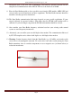
GuiLin FeiYu Electronic Technology Co., Ltd. Aileron Check 5. Holding the plane in your hands roll the plane to the right. The ailerons should give a signal to counter this roll direction as shown below. FY-3ZT IN AUTO BALANCE MODE Right wing automatically moves upwards Left wing aileron automatically moves upwards. Roll left Roll right Right wing aileron automatically moves downwards 6. 7.
GuiLin FeiYu Electronic Technology Co., Ltd. please set ―ELE REV‖ in the ―Control Reverse‖ box. You should now see the correct servo movement after ‗checking‘ the box. RUDDER CHECK: 10. Holding the plane in your hands ―yaw the plane‖ from left to right. The rudder should give a signal to counter the yaw motion as shown bleow: FY-3ZT IN AUTO BALANCE MODE Rotate right Rudder moves to the left Rotate left Rudder moves to the right 11.
GuiLin FeiYu Electronic Technology Co., Ltd. 15. If instead the number reads 2000 and gets smaller as you increase the throttle then check the ―THR REV‖ in the ―Control reverse‖ box: Flight Parameter Setting 1. The following will explains the function of each flight parameter setting: Aircraft Turn Control 2. Roll angle control: indicates the rate coefficient of turning angle control. The higher the value, the greater the turning angle in degrees. This Parameter can be set in range from 0-99 degrees.
GuiLin FeiYu Electronic Technology Co., Ltd. Maximum pitch down setting: - 20 degrees. Range is 0 to 99. Default value: 50. 6. The following table shows Pitch angle control when the plane reaches 10 meter altitude: Value set 30 50 (default) 70 6° 10° 14° Attitude up 10 m 7. Pitch Integrator: Also known as Attitude Deviation Integration. This setting controls the gain to integrate the aircraft current altitude to the target altitude.
GuiLin FeiYu Electronic Technology Co., Ltd. The ‗Rud Turn Control‘ adjusts the gain of the rudder during automated aircraft turning. This gain is linearly proportional. i,e, the value should be adjusted according to the Rudder sensitivity. If your Rudder control sensitivity is high this parameter value should be reduced, and vice versa. For all other mix-control modes, the turning is complete via aileron only. Therefore this ‗Rud Turn Control‘ parameter has no effect on the aircraft. Range :0-99.
GuiLin FeiYu Electronic Technology Co., Ltd. Vibration Detection and Adjustment 1. It is critical that the installation of the autopilot meets the vibration damping requirements. 2. If the installation does not meet the requirements it will affect the accuracy of the attitude stabilization greatly. Excessive vibration can cause unpredictable flight characteristics. 3. Vibration Damping Test Procedure: 1. Connect the power to the system and switch ON the plane. 2.
GuiLin FeiYu Electronic Technology Co., Ltd. Flight Path Setting 1. After the autopilot has attained a lock on the home position, a little red plane will show up on the map at your current position. 2. Set the current location as return point (H. Point) if you wish. 3. To familiarize yourself with flight path setting, try a very simple autopilot flight plan first. 4. In this example, set a ―Box‖ pattern (above). 5. Ensure that the first tests are done well within visual sight of the plane. 6.
GuiLin FeiYu Electronic Technology Co., Ltd. The Debugging of after Take Off 1. This debugging procedure is carried out while the plane is in the air. 2. To carry out this procedure, your plane should be set up well enough to fly straight without constant correction when in manual mode. 3. Always check the Servo Autopilot Control carefully. For more details, please refers to Servo Direction Setting. 4.
GuiLin FeiYu Electronic Technology Co., Ltd. Turning control Adjustment. For Example: From Point A to Point B and then to Point C. B A C A B A Increase Roll angle control. C A Decrease Roll angle control. A A B A C A Increase Course damping. If the plane rolled from side to side during turning, reduce Course damping. A GuiLin FeiYu Electronic Technology Co., Ltd http://www.feiyudz.cn Page 52 E-mail: service@feiyu-tech.
GuiLin FeiYu Electronic Technology Co., Ltd. Route Stability Adjustment 1. ―Rudder Stability‖ is useful. It‘s used to improve the course stability during flying . 2. Notice: The plane will not fly in a straight line if the settings are too high. For an example, flight path from A to B. A B A B C A Increase ―Side Offset damping‖ if plane fly like a ―Big S‖ pattern. A B A B C A Decrease ―Side Offset damping‖ if plane fly in a ―Tight S‖ pattern.
GuiLin FeiYu Electronic Technology Co., Ltd. Additional Note: If your aircraft is normal / traditional fix-wing plane but uses both aileron AND rudder to navigate, the above also applies. You need to set ―Rud Turn Control‖ to adjust heading accuracy when following the planned flight route. Altitude Control Adjustment For an example, Altitude from A to B. A B A B C A If the plane climbs too slowly, increase the ―pitch angle control.‖ A B A If the plane climbs too fast, reduce the ―pitch angle control.
GuiLin FeiYu Electronic Technology Co., Ltd. Speed control: Sets the gain to maintain the actual aircraft speed and the target speed. The higher the gain, the faster the aircraft will react to changes in actual aircraft speed. Speed damping: sets the amount of ‗buffer‘ for throttle change initiation. If there is a change in flying speed, that change must exceed the damping value before throttle is reduced or increased. Generally, you can change the above settings during cruise flight.
GuiLin FeiYu Electronic Technology Co., Ltd. As each aircraft is unique, you will need to fine tune the settings to suit your aircraft’s flight characteristics. ----END--Note: We reserve the right to change this manual at any time! And the newest edition will be shown on our website www.feiyudz.cn. GuiLin FeiYu Electronic Technology Co., Ltd http://www.feiyudz.cn Page 56 E-mail: service@feiyu-tech.