
Typewriter User Manual

A
B
C
2
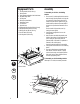
Equipment Parts
1. Punching Handle (PB 300/400 only)
2. Binding Handle
3. Sheet Supporter/Adjustable Comb Guide Selector
4. Adjustable Margin Guide
5. Punching Area
6. Binding Area (Metal Rakes)
7. Waste Paper Drawer
8. Left Side Cover
9. Right Side Cover
10. Disengagable Punching Dies (PB 400/500 only)
11. Margin Depth Setter (PB 400/500 only)
12. Binding Lock Dial (PB 400/500 only)
13. On/Off Switch (PB 500 only)
14. Punching Switch (PB 500 only)
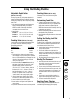
Assembly
To Assemble your PB 300/400 Binding
Machine
1. There are two (2) handles supplied with the machine.
Attach the longer (Punching Handle) to the right side
of the machine by firmly pressing square hole of
handle onto square shaft. To operate correctly, the
handle should be positioned as illustrated.
NOTE: If
the handle is not positioned as illustrated it will not
punch.
Once the handle is fully attached, secure it by
inserting the screw supplied.
2. Carefully attach the Right Side Cover over the
Punching Handle.
3. Attach the shorter, handle (Binding Handle) to the
left-side of the machine by firmly pressing square
hole of handle onto square shaft, position as
illustrated.
NOTE: If the handle is not positioned as
illustrated, it will not bind properly.
Secure the handle by inserting the screw supplied.
4. Carefully attach the Left Side Cover over the Binding
Handle.
5. To mount the Sheet Supporter/Adjustable Comb
Guide Selector, first be sure the two (2) phillips
screws are loose enough so the Supporter/Selector
slides easily into place. Mount Supporter/Selector
and secure by tightening screws.
To Assemble your PB 500 Binding Machine
Follow steps 3-5 for PB 300/400 assembly instructions.
®
PB 300 & PB 400
PB 500
3
5
1
9
6
7
4
2
8
7
8
11
4
2
14
3
5
10
13
9
6
12
10
11
12