Mk III SERIES PROFESSIONAL LOUDSPEAKER ENCLOSURES Refer ence / Owner ’s Manual for 1211 Mk III / 1225 Mk III / 1226 Mk III P/N 053566 REV C
Fender Musical Instruments 7975 North Hayden Road, Scottsdale, Arizona 85258 U.S.A. A Message from the Chairman At Fender, we know the importance of sound reinforcement. From the simple box-top powered mixer to today’s touring concert systems, the need to communicate to make the connection between the performer and the audience is foremost in our mind. Perhaps no other piece of gear can make or break your message or your band’s sound than your sound reinforcement gear.
MK III PROFESSIONAL LOUDSPEAKER SYSTEMS INTRODUCTION All Wood Construction with Sturdy Dado Joints Thank you for purchasing a Mk III Series Loudspeaker System from Fender® Pro Audio. We are sure you will find it both a unique and effective sound reinforcement product, providing years of troublefree service day in and day out.
SPEAKER WIRING AND CONNECTIONS Parallel or series are the two basic ways which multiple speakers can be connected to a single power amplifier. When speakers are connected in parallel, their combined impedance decreases. For speakers wired in series the opposite is true, their combined impedance increases. Thus, when speakers are wired in series, higher impedance speakers in the series draw more power from the amplifier than do speakers in the series with lower impedances.
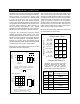
Mk III SERIES SPEAKER CONNECTIONS SETUP SUGGESTIONS In normal operation (using the passive internal crossover), the 1/4" jacks and the Speakon ™ Connectors are wired in parallel allowing any one of the connectors to be used as an input and any other as an output. This allows "daisy chaining" of multiple loudspeakers, eliminating the need for several long, cumbersome runs of speaker cable.
BI-AMP OPERATION UNPOWERED MIXER For versatility and increased headroom, some users may choose to use an active electronic crossover / processor, such as the Fender PCN-2 or PCN-4, with the system. The electronic crossover takes the place of the internal crossover of the speaker system. The "Normal / Bi-Amp" switch on the back of the cabinet must be set to the "Bi-Amp" position.
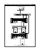
USING A 3-WAY ELECTRONIC CROSSOVER WITH MK III ENCLOSURES UNPOWERED MIXER MAIN OUT MONITOR OUT INPUT PCN-4 ELECTRONIC CROSSOVER A Out SPL-9000 POWER AMP Hi Mk III Cabinet SWITCHES SET TO EXTERNAL CROSSOVER HIGH OUT MID OUT A In B In B Out Hi Mk III Cabinet Low Low A In Bridge Out SPL-9000 POWER AMP Bridge Mono Mode 215s Speakers operated in a bi-amp configuration with a subwoofer (tri-amping) 7 LOW OUT
SPECIFICATIONS MODEL 1211 Mk III 1225 MK III 1226 MK III PART NUMBER 071-1211-200 071-1225-200 071-1226-200 CABINET 5/8" (1.6 cm) Particle Board 3/4" (1.9 cm) Birch Plywood 3/4" (1.9 cm) Birch Plywood CONNECTIONS (2) 1/4" Phone Jacks (2) 1/4" Phone Jacks (2) Speakon™ Jacks (2) 1/4" Phone Jacks (2) Speakon™ Jacks DRIVER Low: 15" (38 cm) woofer 2.5" (6.4 cm) voice coil 15" (38 cm) woofer 3" (7.6 cm) voice coil 15" (38 cm) woofers 3" (7.6 cm) voice coil High: 1" (2.