
Install Instructions

August 2014
06-L00110-000
ATTENTION:
To ensure safe and proper performance, read these
instructions carefully before attempting to install or operate this
Fenwal product. Please retain for future reference.
The shell of each THERMOSWITCH
®
Controller contains the catalog
number, the current rating, the temperature range, and the contact
arrangement.
Controllers that are component recognized or listed by Underwriter’s
Laboratories (UL) or certified by the Canadian Standards Association
(CSA) will also bear the symbol of the approving agency. In addition,
UL component recognized units with temperature ranges up to
500
°
F will have a “4” as the first digit of the Catalog Number.
If the fourth digit of the catalog number is “2” or “7” (e.g., 17021,
17071), the controller is compression operated. Compression units
that close on temperature rise are recommended if overranging is
anticipated. Low temperature units [- 100 to +400
°
F (-73 to
+204
°
C)] can be overranged to 500
°
F (260
°
C) and high temperature
units [-100 to +600°F (-73 to +316
°
C)] overranged to 700
°
F for
intervals not exceeding one hour.
The fifth digit of the catalog number describes whether contacts
open or close on temperature rise. If contacts are open on
temperature rise, the fifth digit of the number is an even number
(17000, 17002, etc.). If contacts close on temperature rise, the fifth
digit is an odd number (17021, 17023, etc.).
INSTALLATION
MOUNTING
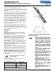
THERMOSWITCH Controllers are supplied in five basic head
configurations - Cartridge, Block Head, Hex Head, Coupling Head
and Circular Flange. See Figure 1.
To avoid restricting shell expansion when making installations in
solid metal blocks, a 0.625 in. diameter reamed hole for 5/8 in.
standard units or a 0.812 in. diameter reamed hole for 13/16 in.
heavy duty units is recommended. See the following specific
controller style listing for additional installation instructions.
Cartridge (Style 1) - Hole should have a short spline to receive
the 0.125 in. diameter locating pin. This prevents the unit from
rotating when the adjusting sleeve is turned. The cartridge style
may be used for surface control if inserted into a Fenwal surface
mounting well (Cat. No. 11100-2).
Block Head (Style 2) - Mounted in a similar manner to the car-
tridge type. If the unit is to be inserted into a reamed hole, mount
two short pins on either side of the hole. The pins should rest
against the sides of the block head to prevent rotation of the unit.
Hex and Coupling Head (Styles 3 and 4) - Installed like any
pipe fitting. If installed in a pipe tee, the tee should be large
enough to allow adequate circulation of the fluid around the tem-
perature-sensitive section of the controller. See Table 1 for maxi-
mum torque values.
Circular Flange (Style 5) - Three holes in flange allow easy
mounting on any flat surface.
Figure 1. Head Configurations
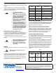
TENSION OR COMPRESSION OPERATED CONTROLLERS
CAUTION STATEMENTS
CAUTION
Excessive torque applied to units may change
temperature settings.
Table 1:
THERMOSWITCH Controller Maximum Torque
Standard (5/8 in. diameter)
35 ft·lb*
(47.5 N·m)
Heavy Duty (13/16 in. diameter)
70 ft·lb**
(94.9 N·m)
*4 ft·lb (5.4 N·m) when Teflon tape lubricant is used.
**8 ft·lb (10.8 N·m) when Teflon tape lubricant is used.
CAUTION
• Certain gases and liquids (including water at
elevated temperature) could be corrosive
and/or cause electrolytic action which could
severely shorten life of controller. Rate of
corrosion or electrolysis is influenced by
many system parameters such as chemical
makeup, temperature of solution, stray
electrical currents, etc. Consult supplier of
your chemicals or Fenwal for application
suggestions. Also, note that Fenwal offers
various platings and Type 321 Stainless steel,
heliarc welded thermowells for added
protection.
• Be sure that there is sufficient but not
excessive room for the installed controller to
expand in diameter and length.
• Insulate head of controller when large
ambient temperature variations may occur.
This precaution is not necessary on junction
box type controllers (Series 17800).
• DO NOT immerse controller into liquids or
gases unless it was specified for that job.
• DO NOT seal controller head with silicone
materials.
• DO NOT thermally shield controller from
medium being controlled.
• DO NOT remove adjusting sleeve or turn it in
farther than necessary for desired operation.
This action may permanently damage
controller.
• DO NOT oil controller. Oil around adjusting
sleeve will flow inside controller,
contaminating contacts.
• DO NOT handle unit with pliers or force it into
position either by hand or with tools.
• DO NOT subject shell of controller to
deformation.
Temperature Adjusting Sleeve
Stud
Contact Points
Non-Expanding
Strut
Anchor Pin
Wall Insulation
Expanding Shell
THERMOSWITCH
®
Temperature Controller Installation Instructions