
Product Overview


F-22-100
July 2016
Spark Electrodes/Flame Sensors
For Gas Ignition Systems
DESCRIPTION
Fenwal electrodes and sensors are an integral part of the
ignition system for gas-fired equipment and ensure
reliable ignition, optimal performance and long service life
over a wide range of operating conditions. Fenwal uses
only high-quality materials such as glazed Alumina
ceramics and certified rod materials suitable for up to
2175° F (1190° C). Fenwal electrodes are RoHS
compliant and CSA certified. Design, configuration and
application are key factors in selecting the proper
electrode. Rely on Fenwal's experience to provide our full
range of gas ignition controls and accessories for your
gas-fired equipment application.
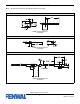
Spark electrodes typically have a 0.125" ±.03” gap
between the high voltage (HV) rod tip and the ground rod
or burner. To facilitate consistent sparking, the gap should
be from a sharp edge to a sharp edge. Position this
"spark gap" at the optimal location in the burner for
reliable lighting of the gas.
IMPORTANT: High efficiency and modulating-condensing
appliances may use mesh burners. These often use
larger spark gaps and may need special consideration in
the system design. Consult FENWAL CONTROLS for
guidance and best practices.
Flame sensors are single rods used in the flame
rectification circuit of the ignition control to confirm the
presence (or absence) of flame. Position this sensor so
that it is well exposed to the flame over some length (not
just the tip) to reliably complete the flame safeguard
circuit.
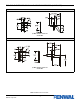
In Local Sense, or "spark and sense" systems, the HV
electrode rod performs both spark and sense functions.
For Remote Sense systems, a separate rod is used to
sense the flame, which may be placed remotely from the
spark electrode, or integrated with it on the same
mounting bracket.
Please refer to pages 2-15 for a wide range of designs
that are in production and available for sampling. Please
contact your local sales representative or Sales Manager
for samples, or detailed dimensions on any electrode of
interest. Fenwal can provide custom design electrodes to
meet your appliance or burner application for annual
volumes ≥ 2000.
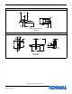
Proper location of electrode assembly is important for
optimum system performance. The electrode assembly
should be located so that the tips are inside the flame
envelope and about 1/2-inch (1.2 cm) above the base of
the flame as shown below.
• Ceramic insulators must not be in or close to the
flame.
• Electrode assemblies must not be adjusted or
disassembled. Electrodes are NOT field-adjustable.
• Electrodes should have a gap spacing of 0.125±
0.031 in (3.12± 0.81 mm), unless otherwise specified
by the appliance manufacturer. If spacing is not
correct, the assembly must be replaced.
• Exceeding temperature limits can cause nuisance
lockouts and premature electrode failure.
• Electrodes must be located where they are not
exposed during normal operation.
IMPORTANT: Always ensure a good ground path that
matches burner ground to control ground.
Consult FENWAL CONTROLS with any questions or to
confirm best solutions for your Ignition problems.