
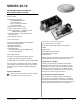
Submittal Sheet


!
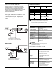
MOUNTING AND WIRING
The 35-72 is not position sensitive and can be mounted
vertically or horizontally. The control may be mounted on
any surface and fastened with #6 sheet metal screws.
Secure the control in an area that will experience a minimum
of vibration and remain below the maximum ambient
temperature of 80°C (175ºF).
All connections should be made with UL approved, 105°C
rated, 18 gauge, stranded, .054” thick insulated wire. Refer
to the appropriate wiring diagram when connecting the 35-72
to other components in the system. High voltage spark
cables and control wiring harnesses are detailed on Pages
5 and 6.
SYMPTOM
Control will not start up
Gas Valve on and no spark
through TFI
Spark on and gas valve off
Flame during trial
for ignition but
no flame sense after
trial for ignition
I
nput Power
Input Current Drain
Gas Valve Rating
Operating Temperature
Flame Sense Voltage
Flame Sense Current
Flame Failure Response Time
Type of Gases
Spark Rate
Moisture Resistance
Size (LxWxH)
Weight
102 to 138 VAC, 50/60 Hz
50mA @ 120 VAC, 60 Hz
1.5A @ 120 VAC
-40°F to +175°F, -40°C to +80°C
45% of line voltage
1.0 microamp minimum
0.8 seconds maximum
Natural, LP and manufactured
Line frequency (50/60 Hz)
Conformal coated to operate to 95% R.H.
Potted to operate up to 100% R.H.
See drawing on back page for details
Integral stand-offs: 2.3 oz
Potted: 6.1 oz
RECOMMENDED ACTIONS
A. Check wiring
B. No voltage @ pin 4, check thermostat
C. Check fuse/circuit breaker
D. Faulty control, consult Fenwal
A. Shorted electrode - re-establish 1/8” gap
B. High voltage cable is disconnected
C. Check wiring
A. Valve coil open
B. Valve wire disconnected
C. Faulty control, check voltage @ pin 2
A. Check electrode position
B. Check high voltage wire and connection
C. Poor ground @ pin 1
D. Check flame current
E. Check remote sensor wire on pin 7
F. Check for proper L1, L2 polarity
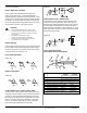
SINGLE SPARK AND SENSE
REMOTE SENSE
TERMINAL
DESCRIPTION
MPIN LOCATION WIRE COLOR
Single Spark and Sense
Burner Ground
Valve Power
Line Neutral
120 Vac Input (Hot)
Valve Neutral
B. Gnd
V1
L2
L1
Not Used
V2
1
2
3
4
5
6
Purple
Brown
White
Black
Yellow
6-Pin Connector
Remote Flame Sense
7-Pin Connector
(same as above plus pin 7)
S1
Remote Flame Sensor
7
Gray
SPECIFICATIONS
TROUBLESHOOTING GUIDE
Terminal Designations
CAUTION:
Label all wires prior to disconnection when servicing the control.
Wiring errors can cause improper and dangerous operation.
A functional checkout of a replacement is recommended.
WARNING:
Operation outside specifications could result in failure of the
Fenwal product and other equipment with injury or death to
people and damage to property.
!
Series 35-72, 120 VAC Direct Spark Ignition Control Page 3
www.fenwalcontrols.com 1-800-FENWAL-1
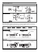
SIX PIN HEADER AMP PART NUMBER 644615-6
ON CIRCUIT BOARD. SEE PAGE 6 FOR MATCHING
CONNECTORS AND WIRING HARNESSES.
SIX PIN HEADER AMP PART NUMBER 64415-7
ON CIRCUIT BOARD. SEE PAGE 6 FOR MATCHING
CONNECTORS AND WIRING HARNESSES.