
Submittal Sheet
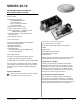


HIGH TEMP
MATERIAL
CSA rated at 2500°F
Steel Cu Flashed
Nickel Plated Steel
Nickel Plated Steel
Alumina
Alumina
Spring Steel
Kanthal APM
Kanthal APM
Kanthal APM
ACCESSORIES
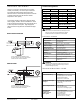
Proper Electrode Location
Proper location of the electrode assembly is important for
optimum system performance. It is recommended that the
electrode assembly be mounted temporarily using clamps or other
suitable means to check the system before permanently mounting
the assembly. The electrode assembly should be located so that
the tips are inside the flame envelope and about 1/2 inch (10 mm)
above the base of the flame. See Figures 3a and 3b.
CAUTIONS:
1. Ceramic insulators should not be in or close to the flame.
2. Electrodes should have a gap spacing of 0.125± 0.031 inch
(3.12 ± 0.81 mm). If this spacing is not correct, the assembly
must be replaced.
3. Exceeding the temperature limits can cause
nuisance lockouts and premature electrode failure.
4. Electrodes must be placed where they are not exposed
to the appliance user in normal operation.
Flame Sensing
Flame sensing is achieved using the principal of flame rectific-ation.
Flame rectification relies on current passing from ground through
the flame to the sense rod. The minimum flame current necessary
to keep the system from lockout is 1.0 μA.
SINGLE SPARK AND SENSE
Figure 3a
REMOTE FLAME SENSE
Figure 3b
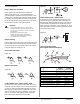
FLAME CURRENT CHECK: SINGLE SPARK & SENSE
To measure flame current, disconnect input voltage, then insert a
0-50 μA DC meter and capacitor in series with the spark electrode
per Figure 4a. Reconnect input voltage and initiate call for heat.
After sparking is complete and flame is established meter should
read 1.0 μA or higher while flame is established. If meter reads
below "0" on the scale, meter leads are reversed. Disconnect
power and reconnect meter leads for proper polarity.
FLAME CURRENT CHECK: REMOTE SENSE
To measure flame current, disconnect input voltage, then insert
a 0-50 μA DC meter inline with flame sense wire per Figure 4b.
Reconnect input voltage and initiate call for heat. After sparking is
complete and flame is established meter should read 1.0 μAor
higher while flame is established. If meter reads below "0" on the
scale, meter leads are reversed. Disconnect power and reconnect
meter leads for proper polarity.
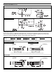
ITEM
#
1
2
3
4
5
6
7
8
9
DESCRIPTION
Mounting Bracket
1/4” Q.C. High Voltage Terminal
3/16” Q.C. Flame Sense Terminal
Spark, H.V. Ceramic Tube
Sense Electrode Ceramic Tube
Press Ring
Flame Sense Electrode
Ground Rod
Spark Electrode, High Voltage
STANDARD
MATERIAL
CSA rated at 1800°F
Steel Cu Flashed
Nickel Plated Steel
Nickel Plated Steel
L-3 Steatite
L-3 Steatite
Spring Steel
Kanthal D
Kanthal D
Kanthal D
!
1
2
3
4
6
7
5
8
9
TYPICAL SPARK ELECTRODE
WITH INTEGRAL REMOTE FLAME SENSE
Figure 4a
Figure 4b
Page 4 Series 35-72, 120 VAC Direct Spark Ignition Control
www.fenwalcontrols.com 1-800-FENWAL-1