
User manual


6
EN
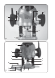
Mounting and removing cutters
Fig. B
Only use cutters with a shaft diameter which
corresponds with the size of the collet. Only use
cutters which are suited for the maximum speed
of the machine. The cutter diameter should not
exceed the maximum diameter (see ‘Technical
VSHFL¿FDWLRQV
Never tighten the collet nut, if there is no router bit
in the collet; the collet may be damaged.
3UHVVWKHVSLQGOHORFNDQGWXUQWKHFROOHW
nut (6) until it engages in the lock. Keep the
spindle lock pressed during this procedure.
2SHQWKHFROOHWQXWXVLQJWKHVSDQQHU
3ODFHWKHFXWWHUVKDIWLQWKHFROOHW
7LJKWHQWKHFROOHWQXWVRWKDWWKHFXWWHULV
locked properly.
2SHQWKHFROOHWQXWZKHQ\RXZDQWWRUHSODFH
a cutter.
Adjusting the parallel fence ruler
The parallel fence is a useful tool for precision
URXWLQJDWD¿[HGGLVWDQFHIURPWKHHGJHRIWKH
workpiece.
3ODFHWKHGHVLUHGFXWWHULQWKHWRRO
6OLGHWKHSDUDOOHOJXLGHZLWKWKHJXLGHURGVLQWR
the baseplate and tighten at the required
measure with the wing bolts
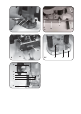
Mounting the template guide
Fig. D
The template guide is a handy aid for cutting a
pattern.
0RXQWWKHWHPSODWHJXLGHRQWKHURXWHU
base (3) using the screws (22).
Mounting the adapter for dust extraction
Fig. E & F
8VHWKHGXVWDGDSWHUIRUWKHH[WUDFWLRQRIGXVW,Q
case the adapter is not mounted on the machine,
follow these instructions.
0RXQWWKHGXVWDGDSWHU)LJ(ZLWKWKH
screws (22) on the cutter sole (3).
3ODFHWKHGXVWWXEHLQWKHGXVWRXWSXW
Fig. F).
3ODFHWKHWXEHRI\RXUYDFXXPFOHDQHURQWKH
dust tube (25, Fig. F).
Keep the outlet of the machine behind
the machine for a good view on the
workpiece.
4. OPERATION
The ON/OFF switch
7RVZLWFKRQWKHWRROSUHVVDQGKROGWKHRQRII
switch (1, Fig. A1, page 2).
,I\RXUHOHDVHWKHRQRIIVZLWFK)LJ$
page 2), the tool will be switched off.
<RXFDQORFNWKHRQRIIVZLWFKE\SUHVVLQJWKH
on/off switch (1, Fig. A1, page 2) and then
button (5, Fig. A1, page 2). The switch lock
FDQEHUHOHDVHGE\EULHÀ\SUHVVLQJWKHRQRII
switch (1, Fig. A1, page 2).
'RQRWSXWWKHPDFKLQHGRZQZKHQWKHPRWRU
is still running. Do not place the machine on a
dusty surface. Dust particles may enter the
mechanism.
Usage tips
$IWHUVZLWFKLQJWKHPDFKLQHRQPDNHVXUHWKH
machine reaches full speed before using it on
the workpiece.
&ODPSWKHZRUNSLHFHDQGPDNHVXUHWKDWWKH
workpiece cannot slide from under the
machine during the cutting activities.
+ROGWKHPDFKLQH¿UPO\DQGPRYHLWHYHQO\
over the workpiece. Do not force the machine.
2QO\XVHFXWWHUVZKLFKGRQRWVKRZDQ\VLJQV
of wear. Worn cutters have a negative effect
RQWKHHI¿FLHQF\RIWKHPDFKLQH
$OZD\VVZLWFKRIIWKHPDFKLQH¿UVWEHIRUH
removing the plug from the wall socket.
Speed Preselection
The required speed can be preselected with the
thumbwheel. Also during running the rotational
speed can be adjusted.
1 – 2 = low speed
3 – 4 = medium speed
5 – 6 = high speed
Max = maximum speed
The required speeds depends on the material and
can be determined by practical testing.
Furthermore router bits with a large diameter
need a lower rotational speed.