OPERATOR’S MANUAL IS1500Z Series Zero-Turn Riding Mower Model Number: 5900605 5900606 5900607 Ferris Industries 5375 North Main Street Munnsville, NY 13409 800-933-6175 Description IS1500ZKAV1944, 19HP, 44” Cut Zero-Turn Riding Mower IS1500ZKAV2148, 21HP, 48” Cut Zero-Turn Riding Mower IS1500ZKAV2552, 25HP, 52” Cut Zero-Turn Riding Mower 5100792 Revision 01 Rev.
Thank you for purchasing this quality-built Ferris product. We’re pleased that you’ve placed your confidence in the Ferris brand. When operated and maintained according to the instructions in this manual, your Ferris product will provide many years of dependable service. This manual contains safety information to make you aware of the hazards and risks associated with this machine and how to avoid them.
Table of Contents Safety Safety Rules & Information ................................2 Identification Numbers .....................................11 Safety Decals .....................................................12 Safety Interlock System....................................13 Features & Controls ..........................................14 Control Functions..................................................14 Operation ...........................................................16 Controls General ...
Safety Rules & Information Safety Operating Safety Congratulations on purchasing a superior-quality piece of lawn and garden equipment. Our products are designed and manufactured to meet or exceed all industry standards for safety. Do not operate this machine unless you have been trained. Reading and understanding this operator’s manual is a way to train yourself. Power equipment is only as safe as the operator.
Safety Rules & Information Safety Slope Operation Operation on slopes can be dangerous. Using the unit on a slope that is too steep where you do not have adequate wheel traction (and control) can cause sliding, loss of steering, control, and possible rollover. You should not operate on a slope greater than a 3.5 foot rise over a 20 foot length (10 degrees). Always mow across slopes, not up and down (to maintain traction on the wheels) and avoid sudden turns or rapid speed changes.
Safety Safety Rules & Information Roll Bar Use Keep the roll bar in the raised position and fasten the seat belt. There is no roll over protection when the roll bar is down! Do not jump off if the mower tips (it is safer to be secured by the seat belt with the roll bar raised.) Lower the roll bar only when necessary (such as to temporarily clear a low overhanging obstacle) and NEVER remove it. Do NOT use the seat belt when the roll bar is down. Raise the roll bar as soon as clearance permits.
Safety Rules & Information Safety Fuel and Maintenance Always disengage all drives, shutoff the engine, and remove the key before doing any cleaning, refueling, or servicing. Gasoline and its vapors are extremely flammable. Do not smoke while operating or refueling. Do not add fuel while engine is hot or running. Allow engine to cool for at least 3 minutes prior to adding fuel. Do not add fuel indoors, in an enclosed trailer, garage, or any other enclosed area that is not well ventilated.
Safety Rules & Information Safety Read these safety rules and follow them closely. Failure to obey these rules could result in loss of control of unit, severe personal injury or death to you, or bystanders, or damage to property or equipment. This mowing deck is capable of amputating hands and feet and throwing objects. The triangle in text signifies important cautions or warnings which must be followed. TRAINING 1.
Safety Rules & Information CAUTION This machine produces sound levels in excess of 85 dBA at the operator’s ear and can cause hearing loss though extended periods of exposure. Wear hearing protection when operating this machine. SLOPE OPERATION Slopes are a major factor related to loss-of-control and tip-over accidents, which can result in severe injury or death. All slopes require extra caution. If you cannot back up the slope or if you feel uneasy on it, do not drive on it.
Safety Rules & Information SERVICE AND MAINTENANCE Safety To avoid personal injury or property damage, use extreme care in handling gasoline. Gasoline is extremely flammable and the vapors are explosive. Safe Handling of Gasoline 1. Extinguish all cigarettes, cigars, pipes, and other sources of ignition. 2. Use only approved gasoline containers. 3. Never remove the gas cap or add fuel with the engine running. Allow the engine to cool before refueling. 4. Never fuel the machine indoors. 5.
Safety Rules & Information ROLL BAR INSTRUCTIONS For models equipped with factory-installed Roll Over Protection System (ROPS). WARNING In order to avoid serious injury or death from roll over, it is important to follow the warnings listed below. OPERATIONAL WARNINGS • Always use the seat belt when the roll bar is in the raised position. • Never use the seat belt when the roll bar is in the down position.
Safety Rules & Information Safety WARNING Failure to properly inspect and maintain the seat belt can cause serious injury or death. INSPECT BUCKLE & LATCH INSPECTION AND MAINTENANCE OF THE ROLL BAR SEAT BELT • The seat belt like the ROLL BAR, needs to be periodically inspected to verify that the integrity has not been compromised through normal machine use, misuse, age degradation, modifications, or a roll over. If the seat belt does not pass all of the following tests, it should be replaced.
Identification Numbers SA M PL Safety Identification Numbers E Identification Tag When contacting your authorized dealer for replacement parts, service, or information you MUST have these numbers. Record your part number, serial number and engine serial numbers in the space provided for easy access. These numbers can be found in the locations shown. NOTE: For location of engine identification numbers, refer to the engine owner’s manual.
Safety Decals Safety SAFETY DECALS This unit has been designed and manufactured to provide you with the safety and reliability you would expect from an industry leader in outdoor power equipment manufacturing.
Safety Icons & Interlock System Safety Icons This unit is equipped with safety interlock switches. These safety systems are present for your safety, do not attempt to bypass safety switches, and never tamper with safety devices. Check their operation regularly. Operational SAFETY Checks Test 1 — Engine should NOT crank if: • PTO switch is engaged, OR • Parking brake is not engaged, OR • Motion control handles are not in the NEUTRAL position.
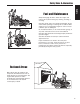
Controls Features & Controls Figure 1. Control Locations CONTROL FUNCTIONS The information below briefly describes the function of individual controls. Starting, stopping, driving, and mowing require the combined use of several controls applied in specific sequences. To learn what combination and sequence of controls to use for various tasks see the OPERATION section. Ground Speed Levers These levers control the ground speed of the rider.
Features & Controls Parking Brake Fuel Tank Cap DISENGAGE Releases the parking brake. ENGAGE Locks the parking brake. To remove the cap, turn counterclockwise. Fuel Level Gauge Displays the fuel level in the tank. Controls Pull the parking brake lever back to engage the parking brake. Move the lever fully forward to disengage the parking brake. NOTE: To start the unit the parking brake must be engaged. PTO (Power Take Off) Switch The PTO switch engages and disengages the mower.
Operation GENERAL OPERATING SAFETY Before first time operation: • Be sure to read all information in the Safety and Operation sections before attempting to operate this tractor and mower. • Become familiar with all of the controls and how to stop the unit. • Drive in an open area without mowing to become accustomed to the unit. WARNING Operation Never operate on slopes greater than 17.6 percent (10°) which is a rise of 3-1/2 feet (106 cm) vertically in 20 feet (607 cm) horizontally.
Operation WARNING If you do not understand how a specific control functions, or have not yet thoroughly read the FEATURES & CONTROLS section, do so now. Do NOT attempt to operate the tractor without first becoming familiar with the location and function of ALL controls. STARTING THE ENGINE 5. After warming the engine, ALWAYS operate the unit at FULL THROTTLE when mowing. In the event of an emergency the engine can be stopped by simply turning the ignition switch to STOP.
Operation ZERO TURN DRIVING PRACTICE The lever controls of the Zero Turn rider are responsive, and learning to gain a smooth and efficient control of the rider’s forward, reverse, and turning movements will take some practice. Operation Spending some time going through the maneuvers shown and becoming familiar with how the unit accelerates, travels, and steers — before you begin mowing —is absolutely essential to getting the most out of the Zero Turn rider.
Operation Practice Turning Around a Corner Practice Turning In Place While traveling forward allow one handle to gradually return back toward neutral. Repeat several times. To turn in place, “Zero Turn,” gradually move one ground speed control lever forward from neutral and one lever back from neutral simultaneously. Repeat several times. NOTE: To prevent pivoting directly on the tire tread, it is best to keep both wheels going at least slightly forward.
Operation MOWING 1. Engage the parking brake. Make sure the PTO switch is disengaged, the motion control levers are locked in the NEUTRAL position and the operator is on the seat. 2. Start the engine (see STARTING THE ENGINE). 3. Set the mower cutting height. 4. Set the throttle to FULL. 5. Engage the PTO by pulling up on the PTO switch. 6. Begin mowing. See Section LC for tips on mowing patterns, lawn care, and trouble shooting information. 7. When finished, shut off the PTO. 8.
Operation When and How Often to Mow The time of day and condition of the grass greatly affect the results you’ll get when mowing. For the best results, follow these guidelines: 1. Mow when the grass is between three and five inches high. 2. Mow with sharp blades. Short clippings of grass one inch or shorter decompose more quickly than longer blades. Sharp mower blades cut grass cleanly and efficiently, preventing frayed edges which harm the grass. 3. Mow at time of day when the grass is cool and dry.
Operation Proper Mulching ATTACHING A TRAILER Mulching consists of a mower deck which cuts and recuts clippings into tiny particles and which then blows them down INTO the lawn. These tiny particles decompose rapidly into by-products your lawn can use. UNDER PROPER CONDITIONS, your mulching mower will virtually eliminate noticeable clippings on the lawn surface. The maximum weight of a towed trailer should be less than 200 lbs (91kg).
Operation RAISE & LOWER THE ROLL BAR To lower the roll bar: C 1. Pull the hair pin clips (A, Figure 13) out of the retainer pins (B). 2. Push or pull the top of the roll bar (C) forward against the rubber stops (D) and remove the retainer pins (B). 3. Lower the roll bar and reinstall the retainer pins and hair pin clips to secure the roll bar in the down position (see insert, Figure 13).
Operation STORAGE Temporary Storage (30 Days Or Less) Remember, the fuel tank will still contain some gasoline, so never store the unit indoors or in any other area where fuel vapor could travel to any ignition source. Fuel vapor is also toxic if inhaled, so never store the unit in any structure used for human or animal habitation.
Regular Maintenance MAINTENANCE SCHEDULE The following schedule should be followed for normal care of your rider and mower. You will need to keep a record of your operating time. Determining operating time is easily accomplished by observing the elapsed time recorded by the hour meter.
Regular Maintenance CHECK TIRE PRESSURES Tire pressure should be checked periodically, and maintained at the levels shown in the chart. Note that these pressures may differ slightly from the “Max Inflation” stamped on the side-wall of the tires. The pressures shown provide proper traction, improve cut quality, and extend tire life. Tire Pressure Front 25 psi (1,72 bar) Rear 15 psi (1,03 bar) CHECKING / ADDING FUEL To add fuel: 1. Remove the fuel cap (see Figure 1). 2.
Regular Maintenance LUBRICATION Lubricate the unit at the locations shown in Figures 16 through 19 as well as the following lubrication points. Grease: • • • • front caster wheel axles & yokes deck lift pivot blocks mower deck spindles mower deck idler arm Use grease fittings when present. Disassemble parts to apply grease to moving parts when grease fittings are not installed. Figure 16. Deck Lubrication Not all greases are compatible.
Regular Maintenance CHECK HYDRAULIC OIL LEVEL 1. Before removing the reservoir cap, make sure the area around the reservoir cap and fill neck of the reservoir is free of dust, dirt, or other debris. 2. Unscrew the reservoir cap (B, Figure 20). 3. Look down the filler neck of the hydraulic oil reservoir (A, Figure 20) and observe the oil level. When cold, the oil level should be approximately 4” (10 cm) below top of the filler neck. 4.
Regular Maintenance SERVICING THE MOWER BLADES 1. Blades should be sharp and free of nicks and dents. If not, sharpen blades as described in the following steps. 2. To remove blade for sharpening, use a 1” wrench on the flats of the spindle shaft while removing the blade mounting bolt with a 15/16” wrench (Figure 22). 3. Use a file to sharpen blade to fine edge. Remove all nicks and dents in blade edge. If blade is severely damaged, it should be replaced. 4. Balance the blade as shown in Figure 23.
Troubleshooting, Adjustment & Service TROUBLESHOOTING While normal care and regular maintenance will extend the life of your equipment, prolonged or constant use may eventually require that service be performed to allow it to continue operating properly. The troubleshooting guide below lists the most common problems, their causes and remedies. See the information on the following pages for instructions on how to perform most of these minor adjustments and service repairs yourself.
Troubleshooting, Adjustment & Service Rider Troubleshooting Continued. PROBLEM CAUSE REMEDY Engine runs, but rider will not drive. 1. 1. Turn valve(s) clockwise to close. Rider drive belt slips. Brake will not hold. Rider steers or handles poorly. 2. 3. 4. 1. 2. Hydraulic release valve(s) in “open” position. Belt is broken. Drive belt slips. Brake is not fully released. Pulleys or belt greasy or oily. Tension too loose. 3. 1. 2. 1. 2. Belt stretched or worn. Brake is incorrectly adjusted.
Troubleshooting, Adjustment & Service TROUBLESHOOTING COMMON CUTTING PROBLEMS PROBLEM CAUSE REMEDY Streaking. 1. 2. 3. 4. 5. 6. 1. Sharpen your blades. 2. Replace your blades. 3. Always mow at full throttle. 4. Slow down. 5. Clean out the mower. 6. Overlap your cutting rows. 3. 4. 5. Blades are not sharp. Blades are worn down to far. Engine speed is too slow. Ground speed is too fast. Deck is plugged with grass Not overlapping cutting rows enough. Not overlapping enough when turning.
Troubleshooting, Adjustment & Service SEAT ADJUSTMENT See Figure 25. The seat can be adjusted forward and back. Move the lever towards the left, position the seat as desired, and release the lever to lock the seat into position. GROUND SPEED CONTROL LEVER ADJUSTMENT The control levers can be adjusted in three ways. The alignment of the control levers, the placement of the levers (how close the ends are to one another) and the height of the levers can be adjusted. Seat Adjustment Lever Figure 25.
Troubleshooting, Adjustment & Service PARKING BRAKE ADJUSTMENT 1. Disengage the PTO, engage the parking brake, stop the engine and remove the ignition key. 2. Raise the seat plate. 3. Locate the brake spring (A, Figure 28). 4. With the parking brake engaged, measure the compressed spring length. The spring should be 1-15/16” - 2” (4,9 - 5,1 cm) when compressed. 5. If the spring is not within this range, release the parking brake and turn the adjustment nut (B) to compress or release the spring. 6.
Troubleshooting, Adjustment & Service REAR SUSPENSION ADJUSTMENT The shock assembly can be adjusted in two ways to allow the operator to customize the ride according to operator’s weight and/or operating conditions. You have the option of adjusting the spring pre-load and/or the upper mounting position. POSITION #1 (FACTORY SET) POSITION #2 Items to consider before adjusting the suspension.
Troubleshooting, Adjustment & Service A B B B C B A Figure 31. Adjust PTO Clutch A. Window B. Adjustment Nut C. .016”-.018” (0,40-0,45mm) Feeler Gauge Figure 30. PTO Clutch Adjustment A. Adjustment Window (Qty. 3, one shown) B. Adjustment Nut PTO CLUTCH ADJUSTMENT Troubleshooting Check the PTO clutch adjustment after the initial 25 hour break-in period and then after every 100 hours of operation.
Troubleshooting, Adjustment & Service RETURN-TO-NEUTRAL ADJUSTMENT To determine if it is necessary to adjust the neutral return, perform the following steps. 1. Disengage the PTO, engage the parking brake and turn off the engine. 2. Move the ground speed control levers into the operating position, pull levers rearward and release. 3. Move the ground speed control levers out towards the neutral position.
Troubleshooting, Adjustment & Service MOWING HEIGHT ADJUSTMENT The cutting height adjustment pin (A, Figure 34) controls the mower cutting height. The cutting height is adjustable between 1-3/4” (4,4 cm) and 5” (12,7 cm) in 1/4” (0,64 cm) increments. 1. Depress the deck lift foot pedal (B) until it locks into the 5” (12,7 cm) position. 2. Place the cutting height adjustment pin in the desired cutting height. 3.
Troubleshooting, Adjustment & Service DECK LEVELING ADJUSTMENT 1. Park machine on a flat, level surface. Disengage the PTO, stop the engine and engage the parking brake. Rear tires must be inflated to 15 psi (1,03 bar); front tires to 25 psi (1,72 bar). 2. To check the lift rod timing, measure and record the distance between the lift pivots and the rod pivots. Repeat for other side of unit. See Figure 36. 3. If the measurements are equal, skip to Step 5.
Troubleshooting, Adjustment & Service HYDRAULIC PUMP DRIVE BELT REPLACEMENT A D 8 3/8” (21,2 cm) E C C F G Figure 40. Hydraulic Pump Drive Belt Replacement A. Pump Drive Belt B. Crankshaft Pulley C. Pump Pulley D. Idler Pulley E. Idler Arm F. Spring G. Spring Anchor Hook Troubleshooting 1. Park the tractor on a smooth, level surface such as a concrete floor. Disengage the PTO, engage the parking brake, turn off the engine, and remove the ignition key. 2.
Troubleshooting, Adjustment & Service MOWER BELT REPLACEMENT To avoid damaging belts, DO NOT PRY BELTS OVER PULLEYS. 1. Park the tractor on a smooth, level surface such as a concrete floor. Disengage the PTO, engage the parking brake, turn off the engine, and remove the ignition key. 2. Lower the mower deck to its lowest cutting position and remove the mower deck guards. 3. Using a 1/2” breaker bar, place the square end in the square hole located in the end of the idler arm (A, Figures 41).
Troubleshooting, Adjustment & Service BATTERY SERVICE WARNING Keep open flames and sparks away from the battery; the gasses coming from it are highly explosive. Ventilate the battery well during charging. Checking Battery Voltage A voltmeter can be used to determine condition of battery. When engine is off, the voltmeter shows battery voltage, which should be 12 volts. When engine is running, the voltmeter shows voltage of charging circuit which normally is 13 to 14 volts.
Troubleshooting, Adjustment & Service THIS HOOK-UP FOR NEGATIVE GROUND VEHICLES To Starter Switch To Starter Switch Jumper Cable Starting Vehicle Battery Discharged Vehicle Battery Jumper Cable To Ground Engine Block MAKE CERTAIN VEHICLES DO NOT TOUCH Figure 43. Jump Starting WARNING For your personal safety, use extreme care when jump starting. Never expose battery to open flame or electric spark – battery action generates hydrogen gas which is flammable and explosive.
Specifications NOTE: Specifications are correct at time of printing and are subject to change without notice. ENGINE: CHASSIS: 19 HP* Kawasaki Fuel Tank Rear Wheels Make Model Horsepower Displacement Electrical System CCA Oil Capacity Kawasaki FH580V 19 @ 3600 rpm 35.7 Cu. in (585 cc) 12 Volt, 13 amp. Alternator, Battery: 340 3.8 US pt. ( 1.8L) w/ Filter 21 HP* Kawasaki Make Model Horsepower Displacement Electrical System CCA Oil Capacity Kawasaki FH641V 21 @ 3600 rpm 41.2 Cu.
Ferris Industries - a division of Simplicity Manufacturing Inc. Owner's Limited Warranty Information (Effective 04/28/2004) Thank you for purchasing Ferris commercial mowing equipment. Please take a few minutes to read this limited warranty information. It contains all the information you will need to have your Ferris mower repaired in the unlikely event that a breakdown covered by this limited warranty should occur.
OPERATOR’S MANUAL IS1500Z Series Zero-Turn Riding Mower Product Quick Specs: ENGINE: BELTS AND BLADES: 19 HP* Kawasaki Make Model Oil Capacity Kawasaki FH580V 3.8 US pt. ( 1.8L) w/ Filter 21 HP* Kawasaki Make Model Oil Capacity Kawasaki FH641V 3.8 US pt. ( 1.8L) w/ Filter 25 HP* Kawasaki Make Model Oil Capacity Kawasaki FH721V 4.0 US pt. ( 1.9 L) w/ Filter CHASSIS: Fuel Tank Rear Wheels Front Wheels Capacity: 6 Gallons (22.7 L) Tire Size: 22 x 11.