OPERATOR’S MANUAL IS5100Z Series N ep o ro t fo du r ct io n Zero-Turn Riding Mower R 61” Model: Model 5901013 Description 33HP Caterpillar Diesel w/ 61” Mower Deck & ROPS (IS5100ZC33D) 72” Models: Tractor 5901011 33HP Caterpillar Diesel w/ ROPS (IS5100ZC33D) Mower Deck 5900591 72” Side Discharge Mower Deck (5100/72) 5900592 72” Rear Discharge Mower Deck (5100/72RD) 5102954 Rev A
Thank you for purchasing this quality-built FERRIS product. We’re pleased that you’ve placed your confidence in the FERRIS brand. When operated and maintained according to the instructions in this manual, your FERRIS product will provide many years of dependable service. This manual contains safety information to make you aware of the hazards and risks associated with this machine and how to avoid them.
Table of Contents Operator Safety .................................................. 2 Troubleshooting, Adjustments & Repair ....... 36 Identification Numbers ..........................................11 Safety Decals ........................................................12 Safety Icons ..........................................................14 Safety Interlock System ........................................15 Troubleshooting the Rider ....................................
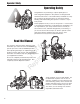
Operator Safety Operating Safety Congratulations on purchasing a superior-quality piece of lawn and garden equipment. Our products are designed and manufactured to meet or exceed all industry standards for safety. Do not operate this machine unless you have been trained. Reading and understanding this operator’s manual is a way to train yourself. Power equipment is only as safe as the operator.
Operator Safety Slope Operation Operation on slopes can be dangerous. Using the unit on a slope that is too steep where you do not have adequate wheel traction (and control) can cause sliding, loss of steering, control, and possible rollover. You should not operate on a slope greater than a 5.4 foot rise over a 20 foot length (15 degrees). Always mow across slopes, not up and down (to maintain traction on the wheels) and avoid sudden turns or rapid speed changes.
Operator Safety Roll Bar Use Keep the roll bar in the raised position and fasten the seat belt. There is no roll over protection when the roll bar is down! Do not jump off if the mower tips (it is safer to be secured by the seat belt with the roll bar raised.) N ep o ro t fo du r ct io n Lower the roll bar only when necessary (such as to temporarily clear a low overhanging obstacle) and NEVER remove it. Do NOT use the seat belt when the roll bar is down. Raise the roll bar as soon as clearance permits.
Operator Safety Fuel and Maintenance Always disengage all drives, shutoff the engine, and remove the key before doing any cleaning, refueling, or servicing. Gasoline and its vapors are extremely flammable. Do not smoke while operating or refueling. Do not add fuel while engine is hot or running. Allow engine to cool for at least 3 minutes prior to adding fuel. Do not add fuel indoors, in an enclosed trailer, garage, or any other enclosed area that is not well ventilated.
Operator Safety Read these safety rules and follow them closely. Failure to obey these rules could result in loss of control of unit, severe personal injury or death to you, or bystanders, or damage to property or equipment. This mowing deck is capable of amputating hands and feet and throwing objects. The triangle in text signifies important cautions or warnings which must be followed. TRAINING PREPARATION R 1.
Operator Safety 23. Use care when approaching blind corners, shrubs, trees or other objects that may obscure vision. 24. To reduce fire hazard, keep unit free of grass, leaves & excess oil. Do not stop or park over dry leaves, grass or combustible materials.
Operator Safety EMISSIONS 1. Engine exhaust from this product contains chemicals known, in certain quantities, to cause cancer, birth defects, or other reproductive harm. 2. Look for the relevant Emissions Durability Period and Air Index information on the engine emissions label. IGNITION SYSTEM (GASOLINE MODELS) 1. This spark ignition system complies with Canadian ICES-002. SERVICE AND MAINTENANCE To avoid personal injury or property damage, use extreme care in handling gasoline.
Operator Safety leaks. Make sure all hydraulic fluid connections are tight and all hydraulic hoses and lines are in good condition before applying pressure to the system. If leaks occur, have the unit serviced immediately by your authorized dealer. 26. WARNING: Stored energy device. Improper release of springs can result in serious personal injury. Springs should be removed by an authorized technician. 27. Models equipped with an engine radiator: WARNING: Stored energy device.
Operator Safety WARNING Failure to properly inspect and maintain the seat belt can cause serious injury or death. INSPECT BUCKLE & LATCH INSPECTION AND MAINTENANCE OF THE ROLL BAR SEAT BELT • The seat belt like the ROLL BAR, needs to be periodically inspected to verify that the integrity has not been compromised through normal machine use, misuse, age degradation, modifications, or a roll over. If the seat belt does not pass all of the following tests, it should be replaced.
Operator Safety IDENTIFICATION NUMBERS Tractor Identification Tag SA M PL E North American Models Mower Deck Identification Tag When contacting your authorized dealer for replacement parts, service, or information you MUST have these numbers. N ep o ro t fo du r ct io n Record your model/serial number and engine serial numbers on the space provided for easy access. These numbers can be found in the locations shown.
Operator Safety SAFETY DECALS This unit has been designed and manufactured to provide you with the safety and reliability you would expect from an industry leader in outdoor power equipment manufacturing. Although reading this manual and the safety instructions it contains will provide you with the necessary basic knowledge to operate this equipment safely and effectively, we have placed several safety labels on the unit to remind you of this important information while you are operating your unit.
Operator Safety 1 2 8 4 N ep o ro t fo du r ct io n 3 9 10 R 5 6 7 13
Operator Safety SAFETY ICONS NORTH AMERICAN SAFETY ICONS The alert symbol is used to identify safety information about hazards that can result in personnal injury. A signal word (DECAL, WARNING, or CAUTION) is used with the alert symbol to indicate the likelihood and the potential severity of the injury. In addition, a hazard icon maybe used to represent the type of hazard.
Operator Safety SAFETY INTERLOCK SYSTEM This unit is equipped with safety interlock switches. These safety systems are present for your safety, do not attempt to bypass safety switches, and never tamper with safety devices. Check their operation regularly. Operational SAFETY Checks Test 1 — Engine should NOT crank if: • PTO switch is engaged, OR • Parking brake is not engaged, OR • Motion control handles are not in the NEUTRAL position, OR • Operator is not on the seat.
Features & Controls N ep o ro t fo du r ct io n FEATURES AND CONTROLS Figure 1. CONTROL FUNCTIONS The information below briefly describes the function of the individual controls. Starting, stopping, driving, and mowing require the combined use of several controls applied in specific sequences. To learn what combination and sequence of controls to use for various tasks see the OPERATION section. Ground Speed Levers These levers control the ground speed of the rider.
Features & Controls Glow Plug Indicator Fuel Level Gauge Displays the fuel level in the tank. Lamp that indicates that the glow plugs are heating. Hold the ignition key in the “HEAT” position until indicator lamp turns off, then turn the key to start. Power Outlet Unit is equipped with a +12VDC, 20A power outlet. Voltage Gauge Gauge measures the output voltage of the engine charging system. Oil Pressure Indicator Lamp that indicates a low oil pressure condition.
Operation CHECKS BEFORE STARTING OPERATION GENERAL OPERATING SAFETY Before first time operation: • Be sure to read all information in the Safety and Operation sections before attempting to operate this tractor and mower. • Check that crankcase is filled to full mark on dipstick. See the engine Operators Manual for instructions and oil recommendations. • Check the radiator fluid level. See engine operator’s manual for instructions. • Check the hydraulic oil level. Refer to REGULAR MAINTENANCE section.
Operation PRIMING THE FUEL SYSTEM B Priming the fuel system fills the fuel filters and removes any air bubbles from the fuel system. This must be performed before the first use, after any fuel filter maintenance or if the fuel system is run dry. A WARNING Fuel leaked or spilled onto hot surfaces or electrical components can cause a fire. To help prevent possible injury, turn the ignition switch off when changing fuel filter or water separator element. Clean up fuel spills immediately.
Operation WARNING If you do not understand how a specific control functions, or have not yet thoroughly read the FEATURES & CONTROLS section, do so now. Do NOT attempt to operate the tractor without first becoming familiar with the location and function of ALL controls. STARTING THE ENGINE 1. While sitting in the operators seat, engage the parking brake and make sure the PTO switch is disengaged and the ground speed control levers are locked in the neutral position. 2.
Operation PUSHING THE RIDER BY HAND DO NOT TOW RIDER Towing the unit will cause hydraulic pump and wheel motor damage. Do not use another vehicle to push or pull this unit. 1. Refer to Figure 3 for hydraulic release valve location. 2. To open the dump valves, turn the right-hand release valve, which is located on top of the righthand pump, counter-clockwise 2 full turns MAX. Then turn the left-hand release valve, which is located on the bottom of the left-hand pump, counter-clockwise 2 full turns MAX.
Operation Smooth Travel ZERO TURN DRIVING PRACTICE The lever controls of the Zero Turn rider are responsive, and learning to gain a smooth and efficient control of the rider’s forward, reverse, and turning movements will take some practice. Spending some time going through the maneuvers shown and becoming familiar with how the unit accelerates, travels, and steers — before you begin mowing —is absolutely essential to getting the most out of the Zero Turn rider.
Operation Practice Turning Around a Corner Practice Turning In Place While traveling forward allow one handle to gradually return back toward neutral. Repeat several times. To turn in place, “Zero Turn,” gradually move one ground speed control lever forward from neutral and one lever back from neutral simultaneously. Repeat several times. NOTE: To prevent pivoting directly on the tire tread, it is best to keep both wheels going at least slightly forward.
Operation MOWING 1. Engage the parking brake. Make sure the PTO switch is disengaged, the motion control levers are locked in the NEUTRAL position and the operator is on the seat. 2. Start the engine (see STARTING THE ENGINE). 3. Set the mower cutting height. 4. Set the throttle to FULL. 5. Engage the PTO by pulling up on the PTO switch. 6. Begin mowing. See Section LC for tips on mowing patterns, lawn care, and trouble shooting information. 7. When finished, shut off the PTO. 8.
Operation When and How Often to Mow The time of day and condition of the grass greatly affect the results you’ll get when mowing. For the best results, follow these guidelines: 1. Mow when the grass is between three and five inches high. 2. Mow with sharp blades. Short clippings of grass one inch or shorter decompose more quickly than longer blades. Sharp mower blades cut grass cleanly and efficiently, preventing frayed edges which harm the grass. 3. Mow at time of day when the grass is cool and dry.
Operation Proper Mulching ATTACHING A TRAILER Mulching consists of a mower deck which cuts and recuts clippings into tiny particles and which then blows them down INTO the lawn. These tiny particles decompose rapidly into by-products your lawn can use. UNDER PROPER CONDITIONS, your mulching mower will virtually eliminate noticeable clippings on the lawn surface. The maximum weight of a towed trailer should be less than 300 lbs (138kg).
Operation RAISE & LOWER THE ROLL BAR To lower the roll bar: C 1. Pull the hair pin clips (A, Figure 11) out of the retainer pins (B). 2. Push or pull the top of the roll bar (C) forward against the rubber stops (D) and remove the retainer pins (B). 3. Lower the roll bar and reinstall the retainer pins and hair pin clips to secure the roll bar in the down position (see insert, Figure 11). D C To raise the roll bar: WARNING A B D Figure 11. Raise & Lower the Roll Bar A. Hair Pin Clip B.
Operation STORAGE WARNING Temporary Storage (30 Days Or Less) Remember, the fuel tank will still contain some fuel, so never store the unit indoors or in any other area where fuel vapor could travel to any ignition source. Fuel vapor is also toxic if inhaled, so never store the unit in any structure used for human or animal habitation.
Regular Maintenance MAINTENANCE MAINTENANCE SCHEDULE & PROCEDURES The following schedule should be followed for normal care of your rider and mower. You will need to keep a record of your operating time. Determining operating time is easily accomplished by observing the hour meter.
Regular Maintenance CHECKING / ADDING FUEL To add fuel: 1. Remove the fuel cap (A, Figure 13). 2. Fill the tank to the bottom of the fill tube. This will leave room in the tank for fuel expansion. Refer to your engine manual for specific fuel recommendations. A 3. Install and hand tighten the fuel cap. 4. Repeat same process for opposite tank. NOTE: The fuel tanks are tied together through a “tee” in the supply lines.
Regular Maintenance CHECK / ADD ENGINE OIL A Refer to Figure 15 for dipstick and oil fill locations. Refer to the engine owners manual for specific engine oil check and fill procedures. Also refer to the engine owners manual for specific engine oil and filter change procedures. CHECK / CHANGE AIR FILTER Refer to the engine owners manual for specific air filter service procedures. B CHECK HYDRAULIC OIL LEVEL NOTE: Do not open the hydraulic oil reservoir unless oil is being added. 1.
Regular Maintenance CHECK ENGINE COOLANT LEVEL WARNING C If engine is warm, DO NOT remove radiator cap. Escaping steam can cause burns. Never remove the radiator cap or radiator reservoir cap while the engine is hot or running. Severe thermal burns or injury can occur by escaping steam or hot coolant. • Do NOT touch hot radiator or open reservoir when engine is running. • Stop and allow engine to cool before removing the radiator cap or the reservoir cap and before changing or adding coolant.
Regular Maintenance LUBRICATION Lubricate the unit at the locations shown in Figure 20 through 24. Grease: Use grease fittings when present. Disassemble parts to apply grease to moving parts when grease fittings are not installed. Not all greases are compatible. Red Grease (P/N 5022285) is recommended, automotive-type hightemperature, lithium grease may be used when this is not available. Figure 22.
Regular Maintenance CLEANING THE BATTERY AND CABLES A B (Note: The tractor equipped with a maintenance-free BCI58 battery) 1. Disconnect the cables from the battery, negative cable first (B, Figure 25). 2. Remove the battery and clean the compartment with a solution of baking soda and water. 3. Clean the battery terminals and cable ends with a wire brush until shiny. 4. Reinstall the battery and reattach the battery cables, positive cable first (A). 5.
Regular Maintenance SERVICING THE MOWER BLADES 1. Blades should be sharp and free of nicks and dents. If not, sharpen blades as described in following steps. 2. To remove blade for sharpening, use a 1” wrench on the flats of the spindle shaft while removing the blade mounting bolt with a 15/16” wrench (Figure 26). 3. Use a file to sharpen blade to fine edge. Remove all nicks and dents in blade edge. If blade is severely damaged, it should be replaced. 4. Balance the blade as shown in Figure 27.
Troubleshooting, Adjustment & Repair TROUBLESHOOTING WARNING While normal care and regular maintenance will extend the life of your equipment, prolonged or constant use may eventually require that service be performed to allow it to continue operating properly. To avoid serious injury, perform maintenance on the tractor or mower only when the engine is stopped and the parking brake engaged. The troubleshooting guide below lists the most common problems, their causes and remedies.
Troubleshooting, Adjustment & Repair Troubleshooting the Rider Continued PROBLEM CAUSE REMEDY Engine runs, but rider will not drive. Hydraulic dump valve(s) in “open” position. Turn dump valve(s) clockwise to close. Torque to 80-120 in.lbs. (9-13.5 Nm) Belt is broken. See Belt Removal and Replacement. Drive belt slips. See problem and cause below. Brake is not fully released. See authorized service dealer. Hydraulic pump drive belt slips. Pulleys or belt greasy or oily. Clean as required.
Troubleshooting, Adjustment & Repair TROUBLESHOOTING COMMON CUTTING PROBLEMS CAUSE Streaking Blades are not sharp. Sharpen your blades. Blades are worn down to far. Replace your blades. Engine speed is too slow. Always mow at full throttle. Ground speed is too fast. Slow down. Deck is plugged with grass Clean out the mower. Not overlapping cutting rows enough. Overlap your cutting rows. Not overlapping enough when turning. When turning your cutting width decreases-overlap more when turning.
Troubleshooting, Adjustment & Repair SEAT ADJUSTMENT See Figure 29. The seat can be adjusted fore and aft. Move the lever forward, position the seat as desired, and release the lever to lock the seat into position. A GROUND SPEED LEVER ADJUSTMENT The control levers can be adjusted in three ways. The alignment of the control levers, the placement of the levers (how close the ends are to one another) and the height of the levers can be adjusted. Handle Alignment Figure 29. Seat Adjustment A.
Troubleshooting, Adjustment & Repair NEUTRAL ADJUSTMENT If the tractor “creeps” while the ground speed control levers are locked in NEUTRAL, then it may be necessary to adjust the control linkage. NOTE: Perform this adjustment on a hard, level surface such as a concrete floor. A 1. Disengage the PTO, engage the parking brake and turn off the engine. 2. Loosen the jam nuts (B, Figure 32) and turn the adjustment linkage (A) to adjust.
Troubleshooting, Adjustment & Repair PARKING BRAKE ADJUSTMENT FRONT 1. Disengage the PTO, stop the engine, block the front wheels, remove the ignition key, and engage the parking brake. 2" - 2-1/8" (5,0 - 5,4cm) 2. Locate the upper brake spring (A, Figure 34) through the opening under the fuel tanks. 3. With the parking brake engaged, measure the compressed spring length. The spring should be 2” - 2-1/8” (5,0 - 5,4cm) when compressed. 4.
Troubleshooting, Adjustment & Repair REAR TIRE CAMBER ADJUSTMENT The rubber bushings in the cast A-arms may stretch and wear with time and adversely affect the angle that the rear tire runs against the ground. 5. Retighten the two (2) 1/2-20 X 3” bolts and the (2) 1/2-20 X 1-3/4” bolts. 6. Reinstall the tire. To evaluate if the rear tire camber should be adjusted, park the machine on a flat and level surface and view the machine from behind.
Troubleshooting, Adjustment & Repair SUSPENSION ADJUSTMENT The shock assembly can be adjusted to vary the amount of pre-load applied to the springs. This allows the operator to maintain the ride height. Use less pre-load for light weight operators. Use more pre-load for heavy weight operators. To adjust the spring pre-load: FRONT Use two hands when adjusting the shock springs. This will prevent the wrench from slipping while pressure is being applied.
Troubleshooting, Adjustment & Repair DECK LIFT ROD TIMING ADJUSTMENT Inner Rod 1. Park machine on a flat, level surface. Disengage the PTO, stop the engine and engage the parking brake. Rear tires must be inflated to 18 psi (1,24 bar); front tires to 25 psi (1,72 bar). d re u as Me st e1 r su a Me 2. To check the inner lift rod timing, measure and record the distance between the inner lift pivots and the inner rod pivots. Repeat for other side of unit. See Figure 39.
Troubleshooting, Adjustment & Repair DECK LEVELING ADJUSTMENT NOTE: Before adjusting the deck level, the deck lift rod timing must be checked and/or adjusted. Figure 42. 2 x 4 Locations B A N ep o ro t fo du r ct io n 1. Park machine on a flat, level surface. Disengage the PTO, stop the engine and engage the parking brake. Rear tires must be inflated to 18 psi (1,24 bar); front tires to 25 psi (1,72 bar). 2. Lock the deck lift pedal in the 6” (15,2 cm) position.
Troubleshooting, Adjustment & Repair 4. 61” Side Discharge: Using a 3/4” combination wrench rotate the spring-loaded idler pulley (A, Figure 45) COUNTER-CLOCKWISE to release the belt tension. 61” Side Discharge Model A C 4a. 72” Side Discharge: Using a 3/4” combination wrench, rotate the spring-loaded idler pulley (A, Figure 45) CLOCKWISE to release the belt tension. 5.
Troubleshooting, Adjustment & Repair Clutch Belt Removal D C B 1. Park the tractor on a smooth, level surface such as a concrete floor. Disengage the PTO, engage the parking brake, turn off the engine, and remove the ignition key. 2. Release the hood latch and raise the hood until it locks in place. 3. Remove the rear belt shield. 4. Remove the 5/16” bolt, washer and nut (C, Figure 48) that fasten the rubber pad to the clutch and unscrew the wire ends that connect the clutch to the electrical harness.
Troubleshooting, Adjustment & Repair Pump Drive Belt Removal 1. Park the tractor on a smooth, level surface such as a concrete floor. Disengage the PTO, engage the parking brake, turn off the engine, and remove the ignition key. B 2. Remove the PTO drive belt from the clutch (see CLUTCH BELT REMOVAL for instructions). 3. Using a 1/2” breaker bar, place the square end in the square hole located in the middle of the idler arm (A, Figures 48).
Troubleshooting, Adjustment & Repair GEARBOX MAINTENANCE Check Gearbox Oil Level A Top 1. Remove fill plug (A, Figure 49) on gearbox. 2. Once plug is removed, oil should seep out of fill plug hole. If no oil drains out, fill with SAE 80-90 weight gear oil until oil starts to seep from hole, then replace fill plug. Changing Gearbox Oil NOTE: The gearbox lubricant should be changed after the first 100 hrs. or 30 days of operation, then after 500 hours or 12 months. 1.
Troubleshooting, Adjustment & Repair BATTERY SERVICE WARNING Keep open flames and sparks away from the battery; the gasses coming from it are highly explosive. Ventilate the battery well during charging. Checking Battery Voltage A voltmeter can be used to determine condition of battery. When engine is off, the voltmeter shows battery voltage, which should be 12 volts. When engine is running, the voltmeter shows voltage of charging circuit which normally is 13 to 14 volts.
Troubleshooting, Adjustment & Repair THIS HOOK-UP FOR NEGATIVE GROUND VEHICLES To Starter Switch To Starter Switch Jumper Cable Starting Vehicle Battery Discharged Vehicle Battery Jumper Cable To Ground Engine Block Figure 50.
Specifications SPECIFICATIONS TRANSMISSIONS: NOTE: Specifications are correct at time of printing and are subject to change without notice. PUMP: * Actual sustained equipment horsepower will likely be lower due to operating limitations and environmental factors. WHEEL MOTOR: ENGINE: 33 HP* CATERPILLAR Make Model Horsepower Displacement Electrical System Oil Capacity Caterpillar 3013E 33 @ 3600 rpm 91.54 Cu. in (1500 cc) 12 Volt, 16 amp. Alternator, Battery: 500 CCA 11.5 Pt. (5.
Ferris Industries - a division of Briggs & Stratton Power Products Group, LLC. Owner’s Limited Warranty Information (Effective 04/28/2004) Thank you for purchasing Ferris commercial mowing equipment. Please take a few minutes to read this limited warranty information. It contains all the information you will need to have your Ferris mower repaired in the unlikely event that a breakdown covered by this limited warranty should occur.
OPERATOR’S MANUAL IS5100Z Series R N ep o ro t fo du r ct io n Zero-Turn Riding Mower