R N ep o ro t fo du r ct io n Supplemental Setup and Operating Instructions and Illustrated Parts Lists for Ferris Zero-Turn Riding Mowers Using Propane Fuel Model Description 5900690 IS3100ZBVP3261, Zero-Turn Riding Mower w/ Propane Fuel 5900691 IS3100ZBVP32, Zero-Turn Riding Mower w/ Propane Fuel 5900789 IS3100ZBVP3261, Zero-Turn Riding Mower w/ Propane Fuel & 16cc Pumps 5900790 IS3100ZBVP32, Zero-Turn Riding Mower w/ Propane Fuel & 16cc Pumps 5900942 IS3100ZBVP3261HT, Zero-Turn Riding Mower
This manual is intended to supplement the operator’s manual included with your machine. There is very important safety, operational and maintenance information in this manual. Read and understand all information in your operator’s manual and this supplement manual before attempting to operate this machine. Save these original instructions for future reference. Table of Contents Operator Safety .................................................. 1 Propane Mower Operating Procedures ...................
Operator Safety Operator Safety WARNING Avoid serious injury or death from operating a mower using propane fuel. Follow mower operating procedures, propane fuel and propane fuel tank filling producedures. MOWER OPERATING PROCEDURES USING PROPANE FUEL PROPANE FUEL TANK FILLING PROCEDURES • A propane fuel tank is a cylinder designed to contain a liquefied petroleum gas (propane) under pressure that is highly flammable.
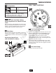
Features & Controls Instrument Control Panel (S/N: 2014953656 & Below) N ep o ro t fo du r ct io n Features & Controls CONTROL FUNCTIONS The information below briefly describes the function of individual controls. Starting, stopping, driving, and mowing require the combined use of several controls applied in specific sequences. To learn what combination and sequence of controls to use for various tasks see the OPERATION section.
Features & Controls FUEL TANK CONTROLS Parking Brake DISENGAGE Releases the parking brake. ENGAGE Locks the parking brake. Pull the parking brake lever back to engage the parking brake. Move the lever fully forward to disengage the parking brake. NOTE: To start the unit the parking brake must be engaged. Deck Lift Pedal, Cutting Height Adjustment Pin & Deck Lift Lock Lever These control the cutting height of the mower deck. Depress the pedal until it locks into the 5” (12,7cm) position.
Operation Operation CHECKS BEFORE STARTING • Check that crankcase is filled to the full mark on the dipstick. See the engine Operator’s Manual for instructions and oil recommendations. • Make sure all nuts, bolts, screws and pins are in place and tight. • Adjust the seat position, and make certain you can reach all controls from operator’s position. • Make sure that the propane tanks are installed correctly and secured tightly. Refer to engine manual for fuel recommendations.
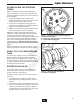
Regular Maintenance RE-INSTALLING THE PROPANE TANKS A NOTE: The propane tank should be installed on the unit so that the fuel shut-off valve and fuel level gauge are pointing toward the rear of the machine by the rear bumper. C B Figure 1. Closing the Fuel Tank Shut-Off Valve A. Fuel Shut Off Valve B. Fuel Supply Hose Fitting (w/ Left Hand Threads) C. Tank Positioning Bracket N ep o ro t fo du r ct io n 1.
Regular Maintenance LEAK TESTING THE FUEL SYSTEM This procedure should only be used when trying to identify the location of a leak. 1. Create a mixture of 50% water and 50% liquid dishwashing soap. 2. OPEN the fuel tank shut-off valve on the left hand propane tanks (turn valve COUNTERCLOCKWISE. Leave the fuel tank shut-off valve on the right tank closed propane tank closed. 3. Using a sponge, rag or small non-metallic brush, apply the soap water mixture at each of the locations circled in Figure 3.
Specifications SPECIFICATIONS TRANSMISSIONS: Specifications are correct at time of printing and are subject to change without notice. (Pumps) ENGINE: Briggs & Stratton* Make Model Displacement Electrical System Oil Capacity Briggs & Stratton 543577-0110-E1 54.62 Cu. in (895 cc) 12 Volt, 20 amp. Alternator, Battery: 340 CCA 2.4 US qt. (2.
R N ep o ro t fo du r ct io n Notes / Notas 8 www.ferrisindustries.
Seguridad del Operador • Revise regularmente la tubería de suministro flexible. Asegúrese de que esté en buenas condiciones. Reemplace los componentes dañados o que presenten fugas. Seguridad del Operador ADVERTENCIA Evite sufrir lesiones graves o la muerte al operar un cortacésped con combustible de propano. Siga los procedimientos de operación del cortacésped, del combustible de propano y de llenado del depósito de combustible de propano.
Funciones y Controles Funciones y Controles N ep o ro t fo du r ct io n Panel de instrumentos de control (S/N: 2014953656 & Abajo) FUNCIONES DE CONTROL La siguiente información describe brevemente la función de cada uno de los controles. Arrancar, detenerse, conducir y podar el césped requieren del uso combinado de varios controles que se aplican en secuencias específicas.
Funciones y Controles CONTROLES DEL DEPÓSITO DE COMBUSTIBLE Freno de mano QUITAR Con eso se quita el freno de mano. ACCIONAR Con eso se fija el freno de mano. Jale la palanca del freno de mano para accionar el mismo y mueva la palanca completamente hacia adelante para quitarlo. NOTA: Para arrancar la unidad, el freno de mano debe estar accionado.
Operación Operación REVISIONES ANTES DE ARRANCAR 6. Después de calentar el motor, opere SIEMPRE la unidad con el acelerador en posición de FULL mientras poda el césped. En caso de emergencia, el motor puede detenerse simplemente girando el interruptor de encendido a STOP. Use este método sólo en situaciones de emergencia. Para apagar el motor de manera normal, siga el procedimiento dado en DETENER EL MONTABLE. DETENER EL MONTABLE 1.
Mantenimiento regular REINSTALACIÓN DE LOS DEPÓSITOS DE PROPANO A NOTA: El depósito de propano se debe instalar en la unidad para que la válvula de corte de combustible y el indicador de nivel de combustible apunten hacia la parte posterior de la máquina cerca del parachoques. C B Figura 1. Cierre de la válvula de corte del depósito de combustible A. Válvula de corte de combustible B. Accesorio de la manguera de suministro de combustible (c/ roscas izquierdas) C.
Mantenimiento regular PRUEBA DE FUGAS DEL SISTEMA DE COMBUSTIBLE Este procedimiento sólo se debe usar al intentar identificar la ubicación de una fuga. 1. Cree una mezcla de 50% de agua y 50% de jabón lavavajillas líquido. 2. ABRA la válvula de corte del depósito de combustible que se encuentra a la izquierda de los depósitos de propano (gire la válvula en sentido CONTRARIO AL DE LAS AGUJAS DEL RELOJ. Deje cerrada la válvula de corte en el depósito de propano derecho. 3.
Especificaciones ESPECIFICACIONES TRANSMISIONES: Las especificaciones son correctas al momento de la impresión y están sujetas a cambios sin previo aviso. Bomba MOTOR Briggs & Stratton Vanguard de 32 Bruto HP* Marca Briggs & Stratton Modelo 543777-0120-E1 Carrera 54.62 pulgadas cúbicas (895 cc) Sistema eléctrico 12 voltios, 20 amp. Alternador, batería: 340 CCA Capacidad de aceite 2.4 US qt. (2.
Supplemental Parts List - Tank Mount Group Illustrated Parts Lists 25 3 19 21 18 19 4 19 20 10 18 18 20 N ep o ro t fo du r ct io n 5 , 27 15 17 9 14 19 8 11 2 22 RH side components 20 20 Propane System Service Parts 18 4 R 6 , 28 18 19 20 18 7 20 18 12 23 19 3 1 16 www.ferrisindustries.
Supplemental Parts List - Tank Mount Group REF NO. PART NO.
Supplemental Parts List - Instrument Control Group S/N: 2014953566 & Below 15 2 3 16 1 Oriented to be read from operator position. 4 7 12 6 5 20 14 8 9 13 N ep o ro t fo du r ct io n 10 11 S/N: 2014953567 & Above 21 R Oriented to be read from operator position. 22 25 23 24 Important Note: Unlabelled components are the same as above. 18 www.ferrisindustries.
Supplemental Parts List - Instrument Control Group REF NO. PART NO.
Supplemental Parts List - Fuel Supply Group (S/N: 2014953566 & Below) FRONT FRONT See Hydraulic Group 1 1 2 3 8 2 4 10 2 11 2 N ep o ro t fo du r ct io n 7 13 12 6 6 REGULATOR 14 15 23 21 20 19 16 15 30 18 24 25 9 R 25 17 14 5 27 22 15 26 19 20 30 28 - “Soft Plug, IMPCO Propane Regulator” ENGINE 20 www.ferrisindustries.
Supplemental Parts List - Fuel Supply Group (S/N: 2014953566 & Below) REF NO. PART NO. QTY DESCRIPTION 5101707 2 TANK, ALUMINUM, PROPANE 2 5023268 4 CLAMP, HOSE 3 5050860X29 1 HOSE, 3/8” PUSH-LOCK, 29.00” 4 5050861X25 1 WIRE LOOM, 5/8” ID, 25” LONG 5 5101430 1 RELIEF VALVE, PROPANE 6 5101570 2 FITTING, 1/4 NPT STREET ELBOW, PLATED STEEL 7 5101440 2 FITTING, 3/8 HOSE BARB X 1/4NPT, BRASS 8 5023267 1 ADAPTER, 90 DEG, 9/16-3/8 BARB 9 5101433 1 HOSE, LOW PRESSURE FUEL X 33.
Supplemental Parts List - Fuel Supply Group (S/N: 2014953567 & Above) FRONT FRONT See Hydraulic Group 8 LH Hydraulic Pump 1 1 2 3 To RH Hydraulic Pump To Oil Cooler 4 2 10 2 11 2 N ep o ro t fo du r ct io n 7 13 12 6 6 REGULATOR 14 15 23 21 20 19 16 14 15 27 17 24 18 25 9 R 25 15 22 26 5 19 20 27 28 - “Soft Plug, IMPCO Propane Regulator” ENGINE 22 Spanish English ES GB www.ferrisindustries.
Supplemental Parts List - Fuel Supply Group (S/N: 2014953567 & Above) REF NO. PART NO. QTY DESCRIPTION 5101707 2 TANK, ALUMINUM, PROPANE 2 5023268 4 CLAMP, HOSE 3 5050860X16 1 HOSE, 3/8” PUSH-LOCK, 16.00” 4 5050861X25 1 WIRE LOOM, 5/8” ID, 25” LONG 5 5101430 1 RELIEF VALVE, PROPANE 6 5101570 2 FITTING, 1/4 NPT STREET ELBOW, PLATED STEEL 7 5101440 2 FITTING, 3/8 HOSE BARB X 1/4NPT, BRASS 8 5023267 1 ADAPTER, 90 DEG, 9/16-3/8 BARB 9 5101433 1 HOSE, LOW PRESSURE FUEL X 33.
Supplemental Parts List - Electrical Schematic - Charging Circuit IGNITION SWITCH POSITION 1. OFF 2. RUN 3.
Supplemental Parts List - Electrical Schematic - Cranking Circuit IGNITION SWITCH POSITION 1. OFF 2. RUN 3.
Supplemental Parts List - Electrical Schematic - Ignition Grounding Circuit / Operator Presence IGNITION SWITCH POSITION 1. OFF 2. RUN 3.
Supplemental Parts List - Electrical Schematic - PTO Clutch Circuit IGNITION SWITCH POSITION 1. OFF 2. RUN 3.
N ep o ro t fo du r ct io n R Notes
N ep o ro t fo du r ct io n R
R N ep o ro t fo du r ct io n Supplemental Setup and Operating Instructions and Illustrated Parts Lists for Ferris Zero-Turn Riding Mowers Using Propane Fuel Briggs & Stratton Power Products Group, LLC. 5375 N. Main Street Munnsville, NY 13409-4003 www.ferrisindustries.