FERRIS OPERATOR’S MANUAL HydroWalk Series Dual Drive Walk-Behind Mowers Powerheads Model Number: DDSKAV15 DDSKAV15CE DDSKAV17 DDSKAV17CE DDSKAV23 DDSKAV23CE 48” Mower Decks Description: Dual Drive w/ 15HP Kawasaki Dual Drive w/ 15HP Kawasaki (Export) Dual Drive w/ 17HP Kawasaki Dual Drive w/ 17HP Kawasaki (Export) Dual Drive w/ 23HP Kawasaki Dual Drive w/ 23HP Kawasaki (Export) Model Number: Description: DDS48 48” Mower Deck DDS48R 48” Rear Discharge Mower Deck (Export) 52” Mower Decks Model Number: DD
FERRIS LIMITED WARRANTY IMPORTANT This warranty shall apply ONLY if the warranty registration form has been completed and returned to Ferris Industries, Inc. within 20 days from the date of delivery. Ferris Industries, Inc. (Ferris) warrants, in accordance with the provisions below, to the original purchaser for the period of twenty-four (24) months from the date of delivery of a Ferris mower that the mower is free from defects in material or workmanship.
Table of Contents Identification Tags ...............................................2 Safety Rules & Information Troubleshooting, Adjustments & Service Troubleshooting the Mower ...................................19 Troubleshooting the Mower Deck..........................20 Mowing Height Adjustment ...................................21 Deck Leveling Adjustment (DDSH models) ..........22 Mowing Height Adjustment (DDSH models).........23 Mower Belt Replacement......................................
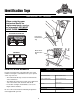
Identification Tags IDENTIFICATION TAG LOCATIONS When contacting your Authorized Dealer for replacement parts, service, or information YOU MUST HAVE THESE NUMBERS. North American Models FERRIS FERRIS INDUSTRIES, INC. MUNNSVILLE, NY 13409 MADE IN THE USA MODEL NO. SERIAL NO. DDSxxxx XXXXX Powerhead Identification Tag Mower Deck Identification Tag CE Models DDSxxxx XXXXX XXXXX MODEL NO. SERIAL NO. DATE XXXXX XXXXX MASS (kg) POWER (kW) FERRIS INDUSTRIES, INC.
Safety Rules & Information Read these safety rules and follow them closely. Failure to obey these rules could result in loss of control of unit, severe personal injury or death to you, or bystanders, or damage to property or equipment. This mowing deck is capable of amputating hands and feet and throwing objects. The triangle in text signifies important cautions or warnings which must be followed. TRAINING • Read, understand, and follow all instructions in the manual and on the unit before starting.
Safety Rules & Information OPERATION • Never run an engine in an enclosed area. • Mow only in the daylight or with good artificial light, keeping away from holes and hidden hazards. • Be sure all drives are in neutral and parking brake is engaged before starting engine. Only start engine from the operator’s position. Use seat belts if provided. • Be sure of your footing while using pedestrian controlled equipment, especially when backing up. Walk, don't run.
Safety Rules & Information CHILDREN EMISSIONS • Engine exhaust from this product contains chemicals known, in certain quantities, to cause cancer, birth defects, or other reproductive harm. • Look for the relevant Emissions Durability Period and Air Index information on the engine emissions label. Tragic accidents can occur if the operator is not alert to the presence of children. Children are often attracted to the unit and the mowing activity.
Safety Decals GENERAL The safety decals below are on your unit. This unit has been designed and manufactured to provide you with the safety and reliability you would expect from an industry leader in outdoor power equipment manufacturing. If any of these decals are lost or damaged, replace them at once. See your local dealer for replacements.
CE Compliance Specs 7
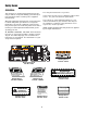
Features & Controls of the Dual Drive Walk-Behind Please take a moment and familiarize yourself with the name, location, and function of these controls so that you will better understand the safety and operating instructions provided in this manual. G B A. B. C. D. E. F. G. H. I. E H F D F Forward Speed Control Lever Reverse Speed Control Levers Ignition Switch Parking Brake Handle PTO Switch Operator Presence Handles Throttle Control Choke Control Neutral Return Pedal A C B Figure 1.
Features & Controls D. Parking Brake Handle SAFETY INTERLOCK SYSTEM The parking brake is applied by pushing DOWN on the parking brake handle until it stops. To release the parking brake, pull UP on the handle until it locks over center. This unit is equipped with safety interlock switches. These safety systems are present for your safety, do not attempt to bypass safety switches, and never tamper with safety devices. Check their operation regularly. E.
Operating the Dual Drive Walk-Behind GENERAL OPERATING SAFETY CHECKS BEFORE STARTING Before first time operation: • Check that crankcase is filled to full mark on dipstick. See the engine Operator’s Manual for instructions and oil recommendations. • Make sure all nuts, bolts, screws and pins are in place and tight. • Fill the fuel tank with fresh fuel. Refer to engine manual for fuel recommendations.
Operating the Dual Drive Walk-Behind WARNING DRIVING THE MOWER The hydrostatic transmission has an infinite number of speeds between full speed forward and reverse, with the faster speeds being achieved by moving the speed control lever and steering control levers farthest in the direction of travel. If you do not understand how a specific control functions, or have not yet thoroughly read the FEATURES & CONTROLS section, do so now.
Operating the Dual Drive Walk-Behind MOWING PUSHING THE MOWER BY HAND Before mowing, set the cutting height as described in the Troubleshooting, Adjustments & Service section. DO NOT TOW MACHINE Towing the machine will cause hydraulic transaxle damage. Do not use another vehicle to push or pull this unit. 1. Engage the parking brake. Make sure the PTO switch is disengaged and the motion control lever is in the NEUTRAL position. 2. Start the engine (see STARTING THE ENGINE). 3. Set the throttle to FULL.
Operating the Dual Drive Walk-Behind STORAGE WARNING Temporary Storage (30 Days Or Less) Never store the unit, with gasoline in engine or fuel tank, in a heated shelter or in enclosed, poorly ventilated enclosures. Gasoline fumes may reach an open flame, spark or pilot light (such as a furnace, water heater, clothes dryer, etc.) and cause an explosion. Handle gasoline carefully. It is highly flammable and careless use could result in serious fire damage to your person or property.
Regular Maintenance MAINTENANCE SCHEDULE & PROCEDURES The following schedule should be followed for normal care of your mower. You will need to keep a record of your operating time.
Regular Maintenance CHECKING / ADDING FUEL WARNING To add fuel: Gasoline is highly flammable and must be handled with care. Never fill the tank when the engine is still hot from recent operation. Do not allow open flame, smoking or matches in the area. Avoid over-filling and wipe up any spills. Do not remove fuel filter when engine is hot, as spilled gasoline may ignite. DO NOT spread hose clamps further than necessary. Ensure clamps grip hoses firmly over filter after installation. 1.
Regular Maintenance LUBRICATION Lubricate the machine at the lubrication points shown in Figures 6 - 11. Use grease fittings when present. Disassemble parts to apply grease to moving parts when grease fittings are not installed. Not all greases are compatible. Ferris Red Grease (P/N 22285) is strongly recommended. Automotive-type high-temperature, lithium grease may be used when this is not available. Figure 8. Blade Spindles Figure 9.
Regular Maintenance BATTERY MAINTENANCE Checking the Battery Fluid NOTE: It is not necessary to check the battery fluid level if machine is equipped with a maintenance-free battery. A 1. Remove the battery box cover to access the battery. 2. Remove the battery filler cap(s) (A, Figure 12). Fluid must be even with the split ring full mark. If not, add distilled water. 3. Reinstall the filler cap(s). Cleaning the Battery and Cables B 1.
Regular Maintenance SERVICING THE MOWER BLADES 1. Blades should be sharp and free of nicks and dents. If not, sharpen blades as described in following steps. 2. Remove the deck guard. 3. Raise the mower deck and secure with jackstands. 4. To remove blade for sharpening, use two (2) 15/16” wrenches to remove the nut from the top of the blade bolt. (Figure 13). 5. Use a file or hand-held grinder, sharpen blade to fine edge. Remove all nicks and dents in blade edge.
Troubleshooting Adjustments & Service TROUBLESHOOTING WARNING While normal care and regular maintenance will extend the life of your equipment, prolonged or constant use may eventually require that service be performed to allow it to continue operating properly. To avoid serious injury, perform maintenance on the mower only when the engine is stopped and the parking brake engaged. The troubleshooting guide below lists the most common problems, their causes and remedies.
Troubleshooting, Adjustment & Service Rider Troubleshooting Continued. PROBLEM CAUSE REMEDY Engine runs, but mower will not drive. 1. 1. Move into drive position. Brake will not hold. 2. 3. 4. 1. 2. 1. Mower steers hard or handles poorly. 1. 2. Transmission drive belt slips. Transmission release lever(s) in “neutral” position. Belt is broken. Drive belt slips. Brake is not fully released. Pulleys or belt greasy or oily. Belt stretched or worn. Internal brake disc on transaxle worn.
Troubleshooting, Adjustment & Service MOWING HEIGHT ADJUSTMENT Height Of Cut The mowing height is determined by three factors: the mount position of the mower deck, the number of blade spacers above the spindle and the number of caster spacers above the caster arm. 1-3/4” 2” 2-1/4” 2-1/2” 2-3/4” 3” 3-1/4” 3-1/2” 3-3/4” 4” Refer to the Height Of Cut chart to the right for the correct settings to obtain the desired height of cut.
Troubleshooting, Adjustment & Service DECK LEVELING ADJUSTMENT (DDSH Models only) 1. Make sure there is one spacer above and below the frame on the front caster shafts and place hairpin clips in the 2” cutting height position (see Figure 17). 2. Rotate the blade on the RIGHT-HAND side (discharge side) until the tip faces the front of the machine. B A Figure 17. Caster Spacers & Hairpin Clip A. B. Caster Spacer Hairpin Clip 3.
Troubleshooting, Adjustment & Service Shimming the Hanger Shafts B Once it has been determined that a shim (P/N 20928) is required, you first must determine which rear hanger shaft requires the shim. A The shim (A, Figure 20) must be placed in between the spacer (B, Figure 20) and the retaining collar (C, Figure 20) on the OPPOSITE side from which the front shaft has movement or slack (see Figure 21).
Troubleshooting, Adjustment & Service MOWER BELT REPLACEMENT AND ADJUSTMENT To avoid damaging belts, DO NOT PRY BELTS OVER PULLEYS. PTO Clutch to Deck Belt A 1. Park the machine on a smooth, level surface such as a concrete floor. Disengage the PTO, engage the parking brake, turn off the engine, and remove the ignition key. 2. Remove the mower deck guard. 3. Remove the rear engine deck guard. 4. Loosen the wing nut (C, Figure 23) to release the belt tension on the deck drive belt (B, Figure 23). 5.
Troubleshooting, Adjustment & Service MOWER BELT REPLACEMENT AND ADJUSTMENT (DDSH Models only) To avoid damaging belts, DO NOT PRY BELTS OVER PULLEYS. 1. Park the machine on a smooth, level surface such as a concrete floor. Disengage the PTO, engage the parking brake, turn off the engine, and remove the ignition key. 2. Remove the mower deck guard. 3. Remove the rear engine deck guard. 4. Loosen the spring compression nut (B, Figure 25 & 26) to release the belt tension. 5.
Troubleshooting, Adjustment & Service TRANSMISSION DRIVE BELT REPLACEMENT B C A D To avoid damaging belts, DO NOT PRY BELTS OVER PULLEYS. FRONT E I 1. Remove the deck drive belt. See MOWER BELT REPLACEMENT AND ADJUSTMENT sections. 2. Remove the grass screen that covers the transmission cooling fans. 3. Remove the clutch anchor bolts (A, Figure 28) that fasten the clutch anchor pad to the anchor. 4. Unplug the PTO clutch from the wire harness. 5.
Troubleshooting, Adjustment & Service TRANSMISSION NEUTRAL & TRACKING ADJUSTMENTS Neutral Adjustment 1. Park the machine on a smooth, level surface such as a concrete floor, away from bystanders and preferably facing a wall. Disengage the PTO, engage the parking brake, turn off the engine, and remove the ignition key. 2. Chock the front caster wheels. Raise the drive wheels off the ground and secure the machine with jack stands. 3. Start the engine and adjust throttle control to SLOW (lowest setting).
Troubleshooting, Adjustment & Service TRANSMISSION MAINTENANCE AND SERVICE B The hydrostatic transmissions are sealed units that require no maintenance other than the following. • Keep the grass screen and transmission cooling fins clear or grass, leaves and debris. • Keep oil level in the reservoirs (A, Figure 30) at the “FULL” line (B, Figure 30). Extra oil in the reservoir will not benefit the machine. • If it is necessary to add oil to the reservoirs, use SAE straight 20 or 30 weight motor oil.
Troubleshooting, Adjustment & Service A B B B C Figure 33. Adjust PTO Clutch B A. B. C. A Window Adjustment Nut .012”-.018” (0,30-0,45mm) Feeler Gauge Figure 32. PTO Clutch Adjustment A. B. Adjustment Window (Qty. 3, one shown) Adjustment Nut PTO CLUTCH ADJUSTMENT WARNING Check the PTO clutch adjustment after the initial 50 hour break-in period and then after every 250 hours of operation.
Troubleshooting, Adjustment & Service BATTERY SERVICE Jump Starting With Auxiliary (Booster) Battery WARNING Jump starting is not recommended. However, if it must be done, follow these directions. Both booster and discharged batteries should be treated carefully when using jumper cables. Follow the steps below EXACTLY, being careful not to cause sparks. Refer to Figure 34. Keep open flames and sparks away from the battery; the gasses coming from it are highly explosive.
Troubleshooting, Adjustment & Service THIS HOOK-UP FOR NEGATIVE GROUND VEHICLES To Starter Switch To Starter Switch Jumper Cable Starting Vehicle Battery Discharged Vehicle Battery Jumper Cable To Ground Engine Block MAKE CERTAIN VEHICLES DO NOT TOUCH Figure 34.
Common Replacement Parts & Accessories COMMON REPLACEMENT PARTS ACCESSORIES Listed below are parts numbers for the more common replacement parts. Use only genuine Ferris replacement parts to assure optimum performance and safety. See your dealer to purchase any of the following accessories for you machine. 50” Snow Blower (SB50) & Hitch (MHW) 48” Deck Belt (PTO to Spindle)............................21723 60” Dozer Blade (DB60) & Hitch (MHW) 48” Deck Belt (Spindle) .....................................
Lawn Care & Mowing Information GENERAL INFORMATION • • • • • • • Proper mowing is an important part of maintaining your lawn in the best possible condition. A healthy and well maintained lawn is better able to resist drought, weeds, and other stresses. But too much maintenance is as detrimental to your lawn as neglect. Proper care for your lawn involves more than just “cutting the grass.
Lawn Care & Mowing Information HOW HIGH TO MOW THE GRASS Cut less than 1/3 Often cutting height is a matter of personal preference. Typically, you should mow the grass when it is is between three and five inches high. The proper cutting height range for a specific lawn will depend upon several factors, including the type of grass, the amount of rainfall, the prevailing temperature, and the lawn’s overall condition.
Lawn Care & Mowing Information WHEN AND HOW OFTEN TO MOW The time of day and condition of the grass greatly affect the results you’ll get when mowing. For the best results, follow these guidelines: l Mow when the grass is between three and five inches high. l Mow with sharp blades. Short clippings of grass one inch or shorter decompose more quickly than longer blades. Sharp mower blades cut grass cleanly and efficiently, preventing frayed edges which harm the grass.
Lawn Care & Mowing Information MOWING METHODS Proper Broadcast Mowing Broadcasting, or side-discharging, disperses fine clippings evenly over the entire lawn. Many golf courses use this method. Your mower has a deep dish deck to allow freer circulation of clippings so they are broadcast evenly over the lawn. ENGINE SPEED & GROUND SPEED FOR BROADCASTING Always operate the engine at full throttle when mowing.
Lawn Care & Mowing Information TIPS On Dealing With Clippings Clippings are beneficial to your lawn. A common misconception about clippings is that they automatically lead to thatch—this is untrue.
Lawn Care & Mowing Information SOLUTIONS FOR COMMON MOWING PROBLEMS ;;;;;;;;; ; ;; ;;;;;;;;; ; ;; ;;;;;;;;; ; ;; Streaking Streaking Streaking is when thin strips of uncut grass are left behind the mower. Streaking is usually caused by operator error or poor blade maintenance.
Lawn Care & Mowing Information ;;;;; ;;;;; ;;;;; ;;;;; ;;;;;;;;;; Uneven Cutting Uneven Cutting Uneven cutting is waviness or smooth troughs in the lawn surface. Uneven cutting is usually caused by mower deck damage or misadjustment.
Common International Symbols PTO Clutch Choke Fast (Throttle) Parking Brake Slow (Throttle) Brake Throttle Mower Cutting Height Adjustment Fuel Headlights Technical Manuals Additional Technical Literature Available Operators Manuals Additional copies of this manual are available, (and as part of our product support commitment, we maintain a stock of printed operators manuals going back many years!) Parts Manuals Fully illustrated parts manuals are also available — these manuals show all of the produc
Notes LC-9