
Instruction Manual

4. Commissioning
4−44
Festo P.BE−SPC200−COM−PDP−E N en 0901c
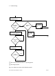
4.7 Sequence plans for the programmer
The following sequence plans will assist you in programming
a higher−order PLC/IPC. They show you how to:
create readiness to operate
start NC records in Record Select mode
start NC programs in Start/Stop mode
quit faults.
The signal names are printed in upper case letters. For
example: READY stands for the READY signal, 1
stands for the
1 signal, 0 stands for the 0 signal.
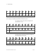
4.7.1 Creating readiness to operate
When the power supply is switched on, the SPC200 performs
the initialization and self test of the connected modules. This
initialization phase can take a certain amount of time, de
pending on the equipment fitted on the system (max. 10 s).
Please note
During this initialization phase no further rising edge may
be generated at the START/RESET input.
After the initialization phase there may be a fault (e.g. hard
ware fault), even if the R EADY output supplies a 1−signal for a
short period. You must therefore wait a further ţ 100ms after
the first recognition
of the 1−signal at the READY output. The
signal at the READY output must then be scanned once again
for a 1−signal (see Fig.4/15 and Fig.4/16; Sequence plan
Creating the readiness to operate").