ATF 55E Circular Saw Instruction Manual Important: Read and understand all instructions before using this tool.
Contents General Safety Rules........................................................................................................................................................................... 3 Specific Safety Rules for Circular Saws........................................................................................................................................ 4 Tool Description...................................................................................................................
General Safety Rules Important: Read and understand all instructions listed below. Failure to heed instructions may result in personal injury, electrocution, or fire hazard. Save These Instructions Work Area ► ► Keep your work area clean and well lit. Cluttered benches and dark areas invite accidents. Do not operate power tools in explosive atmospheres, such as in the presence of flammable liquids, gases, or dust. Power tools create sparks which may ignite the dust or fumes.
Service ► Tool service must be performed only by qualified repair personnel. Service or maintenance performed by unqualified personnel could result in a risk of injury. ► When servicing a tool, use only identical replacement parts. Use of unauthorized parts or failure to follow maintenance instructions may create a risk of electric shock or injury. Specific Safety Rules for Circular Saws !WARNING: Risk of personal injury. Keep hands away from the blade and cutting area.
Tool Description Figure 1 Figure 2 1-a Plunge Release and Trigger Safety Release. Press this lever upward to release the plunge lock and move the sawblade into the work. This lever must be pressed before the power trigger can be engaged. 2-a Plunge Depth Scale. Used with the plunge depth stop (2-b), this sets the depth of cut. 1-b Trigger (On/Off Switch). Pull back on the trigger to turn the saw on. Release the trigger to turn the saw off. 1-c Arbor Lock.
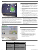
Motor Controls Figure 4 4-a Speed Control Knob. The ATF 55E has electronic variable speed control that maintains a constant speed under varying loads. Turn this dial to change speed from 2100 to 5100 RPM. 4-b Speed Control Pointer. When setting the speed control, line up the numbers on the speed control knob with this pointer. 4-c Motor Power (Green). This green LED indicates when the motor is receiving power. This LED should be ON during normal cutting operations. 4-d Motor Overload (Red).
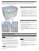
Systainer (System Container) Every Festool product is shipped in its own unique system container, called a "Systainer". This provides protection and storage for the tool and accessories. All Systainers are stackable and can be interlocked together, including stacking and locking atop Festool dust extractors. Figure 6 6-a Carrying Handle. The handle folds flat when not in use. 6-b Cover Latches. These secure the cover and also secure one systainer to another as described below. 6-c Stacking Tabs.
Adjusting the Guide Rail Gibs The guide rail gibs keep the saw's sole plate tightly aligned with the rib of the guide rail system. There is one adjustment gib at the front of the saw and one at the rear. Both need to be adjusted.
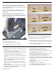
Setting the Blade Perpendicular to the Sole plate This adjustment ensures that cuts are made square to the workpiece surface. This adjustment is completed at the factory and shouldn’t need to be adjusted unless the tool has been modified or serviced. The most accurate method for checking the square of the blade is to make a cut with the saw and examine the resulting cut.
► Adjusting the Blade Position Adjusting the position of the blade with respect to the guide rail system consists of two interrelated adjustments—Blade Distance and Blade Skew. Both of these adjustments are completed at the factory and should be altered only if the saw is damaged, modified, or needs to match other Festool products. 2.
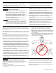
4. After the cut is complete, unplug the saw for safety, but leave it on the guide rail. 5. Lower the sawblade to its maximum depth and examine the gap between the blade and the workpiece using a regular piece of paper as a thickness gauge. ► The front of the blade should be tight to the workpiece. You should not be able to slip the paper between the blade and workpiece. ► The rear of the blade should be 0.15mm away from the workpiece.
Changing the Sawblade Sawblade Checks and Warnings ► ► ► ► ► Use only sawblades that are approved for use with the saw, and appropriate for the type of material being cut. Use only sawblades with a diameter of 160 mm, and an arbor bore of 20 mm. Do not use a sawblade that is bent or warped. Do not use a sawblade with missing or damaged teeth. The hex hey provided with the saw is specifically designed not to cam-out and damage the arbor bolt. Do not use a standard Allen wrench or hex key.
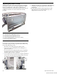
Speed Control The ATF 55E has electronic speed control so the speed of the blade remains constant regardless how much the motor is loaded. The speed of the motor should be set according to the type of material being cut. Figure 18 18-a Speed Control Knob 18-b Pointer 18-c Power Indicator Adjustment Settings Turn the speed control knob (18-a) so the speed indicator lines up with the pointer (18-b). Material Soft wood products and veneer plywoods Hardwood products prone to burning when cut (i.e.
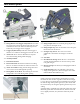
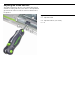
Dust Extraction Figure 21 Figure 22 21-a Diverter Storage 21-b Dust Port 21-c Retaining Ribs Figure 22 shows the diverter (22-a) installed and directing the dust to the side. The diverter can be rotated so dust can be directed downward or to the side. The ATF 55E can be used with the standard dust extraction diverter or with a vacuum system. When not in use, the diverter is stored on the sole plate of the saw (21-a). For best performance, a vacuum system is recommended.
Safety Checks ► ► ► ► Inspect the saw for loose parts and for proper operation. Inspect the area underneath the cutting path to make sure you will not cut through other objects. Make sure the power cord is behind the saw and not within the cutting path. Before beginning the cut, make sure the sawblade is at operating speed. ► ► During the cut, if the "Motor Overload" light turns on, slow down the feed rate of the saw (see Motor Controls on page 6). Push the saw forward to cut.
Troubleshooting Symptom Motor does not start and no indicator lights come on Motor does not start but the power indicator (Green LED) is illuminated The overload light (Red LED) comes on frequently The saw makes a "Growling" sound when it is first turned on or idling. The saw makes wavy cuts Saw cuts are burning Excessive chipping on the lower edge of the cut Excessive chipping on the top edge of the cut 16 Possible Causes Check that the cord is properly plugged into an outlet.
Maintenance Routine Maintenance Any maintenance or repair work that requires opening of the motor or gear housing should be carried out only by an authorized Customer Service Center (name supplied by your dealer)! Maintenance or repair work carried out by an unauthorized person can lead to improper connection of electrical wires or other components, which can result in injury.
Changing the Motor Brushes This procedure should be completed only by an authorized Festool service representative. Opening the motor cover WILL void your warrantee. This procedure is presented as informational only. The motor brushes are graphite bars that provide an electrical connection between the motor controller and the rotating armature. The brushes wear over time and need to be replaced.
Accessories Sawblades Description Purpose Coarse Crosscut Ripping (Panther) With a low tooth count and a high hook angle, this blade easily cuts through general construction materials. The high hook angle of the Panther blade makes for effortless ripping without burning the cut.
Guide Rail Accessory Kit Item Number: 492 396 Contains: Miter Gauge, Splinter Guard, Guide Stop, Cord Guide, Guide Rail Connection Bars, Guide Rail Clamps, Systainer. Universal Tool (Toolie) Item Number: 490 833 This single tool contains all of the drivers and keys necessary to adjust any Festool tool. (Exception: Note that the arbor bolt on the saw uses a special hex key for changing blades. Using the Toolie can damage the arbor bolt.) Contains: 2.5, 4.0, 5.0, 6.
Warranty Conditions of 1+2 Warranty You are entitled to a free extended warranty (1 year + 2 years = 3 years) for your Festool power tool. Festool shall be responsible for all shipping costs during the first year of the warranty. During the second and third year of the warranty the customer is responsible for shipping the tool to Festool. Festool will pay for return shipping to the customer using UPS Ground Service. All warranty service is valid 3 years from the date of purchase on your receipt or invoice.