
Operation Manual


14
C 12 Li, C 15 Li
GB
–
Protect the battery pack from excessive heat or
constant heat sources such as sunlight or naked
flames.
There is a risk of explosion.
–
Never use water to extinguish burning li-ion
battery packs, always use sand
or a fire blanket.
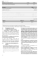
5.3 Emission levels
Levels determined in accordance with EN 60745 are
typically:
Vibration emission value a
h
(vector sum for three
directions) and uncertainty K measured in accor-
dance with EN 60745:
The specified emissions values (vibration, noise)
– are used to compare machines.
– They are also used for making preliminary esti-
mates regarding vibration and noise loads during
operation.
– They represent the primary applications of the
power tool.
Increase possible for other applications, with other
insertion tools or if not maintained adequately. Take
note of idling and downtimes of machine!
6Operation
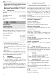
6.1 Changing the battery pack [2]
The battery packs in the BPC series are also
suitable for use with the cordless drills T 12+3/
T 15+3 of the same voltage.
The capacity display
[1-10]
shows the charge sta-
tus of the battery pack. If the capacity display is
flashing the battery pack is empty. The capacity in-
dicator does not work with NiCd and NiMH battery
packs.
6.2 Charging the battery pack [3]
Battery pack is ready for use immediately upon
delivery and can be charged at any time.
The charger TRC 3 can be used to charge all Festool
battery packs of the BPS and BPC series. The char-
ger automatically detects the type of the inserted
battery (NiCd, NiMH or LiIon). A microprocessor
controls the charging process in line with the
charging state, temperature and voltage of the bat-
tery pack.
The LED
[3-1]
on the charger indicates the respec-
tive operating status of the charger.
LED yellow - lit continuously
Charger is ready to use.
LED green - flashing quickly
Battery pack is charged to maximum capacity.
LED green - flashing slowly
Battery pack is charged with reduced current, LiIon
is charged to 80 %.
LED green - lit continuously
Battery pack is fully charged, or charging is not
started again, because the battery is charged to
more than 80 %.
LED red - flashing
General fault display, e.g. incomplete contact, short
circuit, battery pack faulty, etc.
LED red - lit continuously
Battery temperature is outside the permitted
range.
6.3 Charger wall mount
The charger TRC 3 has two elongated holes on its
back. It can be mounted on a wall using two screws
(e.g. round head or flat head screw with shank di-
ameter of 5 mm) (see Fig.
[3]
).
7Settings
7.1 Changing direction of rotation [1-8]
• Switch to the left = clockwise rotation
• Switch to the right = counterclockwise rotation
7.2 Changing gear [1-4]
• Gear switch forwards (digit 1 visible) = 1st gear
• Gear switch to rear (digit 2 visible) = 2nd gear
7.3 Fastening
Adjust the switch so that its marking
[1-7]
faces the
screw symbol
[1-6]
.
Adjust the torque accordingly at the torque wheel
[1-1]
.
Position 1 = low torque
Position 25 = high torque
Sound pressure level L
PA
= 65 dB(A)
Noise level L
WA
= 76 dB(A)
Measuring uncertainty allow-
ance
K = 3 dB
CAUTION
Operating noise
Damage to hearing
Use ear protection!
Drilling in metal a
h
< 2,5 m/s
2
K = 1,5 m/s
2
Screwing a
h
< 2,5 m/s
2
K = 1,5 m/s
2