
accessories PRECISIO Owner's manual


8
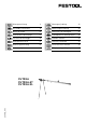
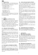
1 Trimming attachment
The trimming attachment (Order-No. 488 063)
consists of a base support (1.1) and a stop ruler
with the following main parts:
profi le rail (1.4), -
extending end piece (1.3) -
with tape measure (1.2), -
adjustable intermediary piece (1.10), -
adjustable stop (1.5), -
tape measure clamp (1.7) -
and workpiece support (1.6). -
If used with the sliding table CS 70 ST, only the
stop ruler (Order No. 488 842) without base sup-
port is required.
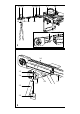
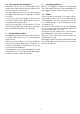
2 Assembly of the stop ruler
2.1 Fastening to mitre fence (Fig. 1)
The stop ruler is fastened to the mitre fence
(1.8) of your CS 70 EB, whereby this is normally
mounted on the left of the circular saw or the
sliding table.
Remove the profi le rail of the CS 70 EB from the
mitre fence and replace with the profi le rail (1.4)
of the stop ruler.
2.2 Assembly of the base support (Fig. 2)
The base support supports the stop ruler when
working without a sliding table.
To assemble release the two rotary knobs (2.1)
on the workpiece support (2.8) until the two ad-
ditional legs (2.3) can be inserted into the pipe
clamp (2.4).
Insert the additional legs until the base support is
the same height as your CS 70 EB and then tighten
the additional legs with the rotary knobs (2.1).
Screw the fastening plate to the lower groove of
the stop ruler by its slit (2.5) using the rotary knob
(2.2) and the feather key (2.7) so that the two cams
(2.6) engage in the groove.
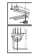
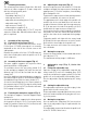
2.3 Fastening the workpiece support (Fig. 3)
The workpiece support is used to support longer
workpieces.
Screw the workpiece support to the lower groove
of the profi le rail by its slit (3.1) using the rotary
knob (3.2) and the feather key (3.3) so that the two
cams (3.5) engage in the groove.
2.4 Adjusting the stop ruler (Fig. 4)
Insert the tape measure with holder (1.12) into the
end piece and pull the tape measure through the
upper groove (1.13) of the end piece, intermediary
piece and profi le rail.
To prevent the tape measure from making contact
with the saw blade, this starts at 30 mm.
The gap between the front edge of the profi le rail
and the rim of the saw blade thus has to be ad-
justed to 30 mm as follows: pull the tape measure
(4.1) 30 mm over the end of the profi le rail (4.2)
and fi x with the tape measure clamp (4.3).
Set the mitre fence to a right-angled cut and push
the profi le rail until the end of the tape measure
touches the sides of the saw blade cutting edges
(4.4).
Clamp the profi le rail tight with the rotary knob
(4.5) and lock the tape measure so that its end is
fl ush with the front edge of the profi le rail.
The tape measure now shows the exact gap to
the saw blade.
2.5 Moving the stop ruler
Loosen the rotary knob (1.9) to extend and retract
the end piece (1.3).
The maximum cutting range is 2050 mm.
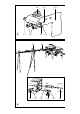
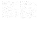
3 Adjustable stop (Fig. 5, Order No.
488 560)
3.1 Fitting the adjustable stop
Open the clamp for the adjustable stop with the
rotary knob (5.1) until the clamping piece (5.5)
can be inserted into the upper groove (3.4) of the
profi le rail or the adjustable intermediary piece.
Fix the adjustable stop by tightening the rotary
knob.
3.2 Setting the adjustable stop
The adjustable stop can be set with no play in the
groove with the two screws (5.6).
Fit the adjustable stop and tighten the two screws
until this can be moved with no play, but still eas-
ily, in the groove.
3.3 Moving the stop plate
You can mount the stop plate (5.3) on the other
side of the adjustable stop if required with the
screw (5.4).
The adjustable stop can be fi tted to the profi le rail
of the CS 70 EB’s mitre fence.