Kapex® KS 120 Miter Saw Sliding Dual Compound Miter Saw Supplemental User’s Manual WARNING To reduce the risk of serious or fatal injury, read and understand all safety precautions and instructions in this manual before using this tool.
Limited Warranty 30 Day Money Back Guarantee We are so confident that you will thoroughly enjoy our tools, that we offer a 30 day money back guarantee. If you are not completely satisfied, your full purchase price will be refunded, excluding all freight charges. 1+2 Limited Warranty Festool USA offers a 3-year limited warranty, one of the longest in the industry. This warranty is valid on the pre-condition that the tool is used and operated in compliance with the Festool operating instructions.
Contents Limited Warranty .............................................2 30 Day Money Back Guarantee ......................... 2 1+2 Limited Warranty ..................................... 2 Conditions of 1+2 Limited Warranty .................. 2 Repairs ......................................................... 2 Returns......................................................... 2 Liability Statement ......................................... 2 Proprietary Notice...........................................
General Power Tool Safety Warnings WARNING! Read all safety warnings and instructions. Failure to follow the warnings and instructions may result in electric shock, fire, and serious or fatal injury. CAUTION! Laser Radiation. This product contains a Class II laser. Do not look directly into the laser beam. Power ≤ 1mW, Wavelength: 640 to 660 nm Save all warnings and instructions for future reference. Work Area Safety ► ► Keep your work area clean and well lit.
Service ► To reduce the risk of serious or fatal injury, never open the motor housing. Have your power tool serviced only by a qualified repair person using only identical replacement parts. ► Any repairs to the laser must be carried out by the laser manufacturer or by an authorized agent of the laser manufacturer. Never attempt to replace the laser on this tool with a different type of laser.
Intended Use The Kapex miter saw is intended to cut wood, plastic, aluminum, and similar materials. All applications beyond this are regarded as improper use. The tool should not be altered or used for any other purpose other than as specified in these operating instructions. Using the tool in contravention to this manual may lead to injury and will void your warranty. The user shall be responsible and liable for accidents, injuries, and property damage resulting from misuse or abuse of this tool.
Functional Description (continued) Item Name or Description Ref. Page(s) Item Name or Description Ref.
Setup Setting Up a New Miter Saw Congratulations on your purchase of a new Kapex Sliding Dual Compound Miter Saw. Before using your new miter saw, make sure you fully read and understand all of the instructions, precautions, and safety information presented in this manual. ► For a more permanent installation, the Kapex saw is equipped with 4 bolt holes, to be used with ¼-20 (M6) bolts to securely bolt the saw to a work table.
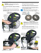
Changing Sawblades WARNING! To reduce the risk of injury from contact with a moving part, always unplug the saw before changing blades. 1. 2. 4. Without pushing down on the trigger lock, pull up on the trigger to release the blade guard. 5. Raise the blade guard out of the way and remove the outboard arbor flange and sawblade from the arbor. 6. Inspect the friction lining on the two arbor flanges. If the lining is damaged, replace the flanges, as this can cause the sawblade to wobble.
Transporting the Saw When The Kapex miter saw is collapsed for transport, it is very well balanced and easily carried using the integrated carrying handles. 1. Unplug the saw and coil the power cord on the reel at the rear of the saw. 4. Set the miter angle to 60° and push down on the miter lock lever. 5. Pick up the saw from the rear by grasping the two handle points as shown below. WARNING! To reduce the risk of unexpectedly starting the saw, make sure the saw is unplugged. 2.
Basic Operation Setting the Motor Speed The Kapex saw has electronic speed control with soft-start circuitry. The electronic controller will maintain the motor speed even as the load changes. The speed control is infinitely variable from 1400 to 3400 RPM. The optimal speed of the saw is predominately determined by the type of material being cut.
Using the Hold Down Clamp The hold down clamp fits in a socket on either the left or right sides of the saw. To insert or remove the clamp, rotate it to the rear to unlock it from the socket, as shown in the first image below. To lock the clamp in its socket, rotate it to the forward position, as shown in the center image below. To secure the workpiece, press down on the green knob and rotate the locking handle down, as shown in the image on the right, below.
Setting the Bevel Angle A beveled cut is where the saw head is tilted to the left or right from vertical. The Kapex saw is capable of beveling up to 47° to the left and right. 3. Rotate the bevel adjustment knob until the bevel index pointer is pointing to the desired angle. (There is a duplicate pointer on either side of the saw.) The bevel range selector engages a series of angle stops. The selector has three settings.
Setting the Depth Limit The depth limit is used for making partial cuts that do not cut all the way through the workpiece, such as making dados. When the depth limit is engaged, the sawblade’s vertical travel is limited from going below the preset height. The height is easily adjustable by turning the depth limit knob. Turning the knob clockwise ¼-turn raises the sawblade by approximately 1 mm (0.040”), and turning it counterclockwise lowers the sawblade. To engage the depth limit, pull the knob forward.
Using the MiterFast Tool The MiterFast™ angle transfer tool converts a corner angle measurement into a miter setting. The miter line in the center of the tool is always at the midpoint of the two angle arms, and when lined up with the saw’s laser, provides the proper miter angle for the measured corner. 4. Place the MiterFast tool on the saw with one of the arms up against the fence. 5. Turn on the laser for the saw. (Refer to Using the Laser Guides on page 11.) 6.
Using the Bed Extensions and Crown Stops The optional bed extensions provide a useful platform for using additional workpiece control accessories as well as extending the size of the bed of the Kapex saw. The optional bed extension accessory includes the crown stop, as shown to the upper right. The extension can be mounted to the left side or right side of the saw’s bed, or if two are used, to both sides simultaneously.
Cutting Techniques There are three basic cutting techniques for sliding miter saws, but only two are proper and authorized. These are Chop-Cut, Push-Cut, and the improper method is a Pull-Cut. that the sawblade is cutting the wood in two different manners, and there will frequently be a rough edge at the transition from one type of cut to the other.
Miter Cuts Miter cuts are used when a board needs to be cut at an angle across its width. The most common application for a miter cut is for joining two boards to form a corner without endgrain showing. The miter angle is one-half of the corner angle. So for a 90° corner, for example, the miter angle is 45°. ► ► When marking the length of the workpiece, use a sharp pencil to draw a thin line. The thicker the line, the more difficult it will be to cut accurately on the line.
Depth Limited (Dado/Half-Lap) Cuts Half-Lap Joint WARNING! Never attempt to install or use a dado blade in the Kapex saw. Using either a stacked-dado or wobble-dado blade will exceed the capacity of the arbor, and the blade may impact the saw’s guards, resulting in personal injury and damage to the saw. A dado is a special type of cut where the depth of the cut does not go all the way through the workpiece.
Compound Miter Cuts Compound miter cuts are where the saw is both in a miter position and a bevel position at the same time. There are several applications for compound miter cuts, but cutting crown moulding and sloped miters are common examples. The example below shows a very simple birdfeeder roof. Slope The Slope angle is the angle that each piece makes with respect to the base of the corner, such as the ceiling or floor in the examples provided here.
necessarily coincide with the “points” or “Tails” of the moulding. The slope is measured from the back-side of the moulding, regardless how long the tails of the moulding may extend (see image below). Determining the Slope of Crown Moulding As was mentioned previously, the slope of a crown moulding is the compliment of its ”Spring Angle” (the spring angle is measured relative to the wall, and the slope is measured relative to the ceiling).
Crown Moulding There are several methods for cutting crown moulding, and each method has its benefits depending on the specific application. The most common method for cutting crown moulding is to use a standard miter cut, where the moulding is tilted against the fence of the saw. For unusual situations, or when the moulding is too large to fit against the fence, compound miters are used. In some applications, inside corners are made using a method called “coping.
Adding Auxiliary Fence Faces Auxiliary fence faces can be added to the Kapex fence. One of the primary benefits of adding fence faces is to create a zeroclearance fence opening for cutting smaller workpieces. The term, “zero-clearance” means that there is no gap between the sawblade and the fence. This is achieved by cutting the auxiliary fence to final length after it is installed. ► ► Option 1: Place a washer on the back of each mounting screw.
Calibration and Adjustment The Festool Kapex miter saw comes fully calibrated from the factory and should not require further calibration out of the box or after normal use. The following calibration techniques should only be necessary in the event that your saw is knocked out of alignment, such as can happen during frequent, or unsecured transport. Use these procedures only when your saw needs service.
Measuring the Error Before adjusting the saw, you first need to measure whether it is accurately calibrated to begin with. If you attempt to exceed the factory calibration threshold, you may end up actually making the saw less accurate. 1. 10. Measure the width of the fourth offcut at both ends (as labeled “Right” and “Left”). These two measurements are critical, so use the best method you can. Number the sides of the scrap piece of wood from 1 to 4, starting with the best edge.
Calibrating the Bevel Angle Calibrating the bevel angle uses the same 4-cut method described in the Calibrating the Miter Angle procedure on page 24. Refer to the discussion on page 24 for an explanation of the method. 2. On the #1 side, which will eventually become the final calibration offcut, label it “Left” and “Right” as shown. Do this regardless whether the cut is made on the left or right side of the sawblade.
11. Measure the length of the fourth offcut. The accuracy of this measurement is not critical, so a standard tape measure or ruler will suffice. 1. 12. Measure the width of the fourth offcut at both ends (as labeled “Right” and “Left”). These two measurements are critical, so use the best method you can. Using the hex key stored on the cord reel, slightly loosen the two adjusting screws located behind the cord reel shown below. 2.
Calibrating the Lasers In order to calibrate the lasers, you will need to puncture the decal on the side of the saw. The 2.5mm adjustment screw openings are identified by the small circles on the decal. The 2.5 mm hex key is shipped with the saw and is located in the Styrofoam packing material. ► ► ► The Tilt adjustment is used to ensure the lasers are pointing parallel to the sawblade, so they trace out the same line regardless whether the saw is raised or lowered.
Troubleshooting Symptom Motor does not start Lasers do not work Possible Causes ► Check that the cord is properly plugged into an outlet. ► Make sure the outlet has power. Check the circuit breaker or try another outlet. ► If used with a Festool dust extractor, make sure the selector switch is pointing to "Auto". The auxiliary outlet on the dust extractor has power only when the selector is at Auto. ► Inspect the power cord (including extension cords) for damage or missing prongs.
Optional Accessories Sawblades Combination Blade Tooth Type Hook Angle Item Number Description ATB, 60 teeth -5° 494 604 This is the standard blade that comes with the saw. With a moderate tooth count and ATB tooth grind, this blade provides good results when a single blade is needed for general purpose cutting. The blade incorporates asymmetrical tooth spacing to reduce harmonic vibration.
MFT/3-Kapex Table 495 565 The MFT/3-Kapex work support table is specifically designed for use with the Kapex saw. It is slightly shorter than a standard MFT/3 and also has additional mounting holes for placing the saw. The saw may be positioned close to the front edge, close to the rear edge, more to the left, or more to the right. The height of the MFT/3-Kapex is lower so the Kapex is at a more comfortable working height.
Kapex KS120 Miter Saw