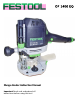
OF 1400 EQ Plunge Router Instruction Manual Important: Read and understand all instructions before using this tool.
Warranty Conditions of 1+2 Warranty You are entitled to a free extended warranty (1 year + 2 years = 3 years) for your Festool power tool. Festool shall be responsible for all shipping costs during the first year of the warranty. During the second and third year of the warranty the customer is responsible for shipping the tool to Festool. Festool will pay for return shipping to the customer using UPS Ground Service. All warranty service is valid 3 years from the date of purchase on your receipt or invoice.
Contents Warranty ..............................................................................2 Conditions of 1+2 Warranty .........................................2 Festool Limited Warranty .............................................2 Liability Statement .........................................................2 Proprietary Notice..........................................................2 General Safety Rules...........................................................4 Work Area Safety .................
General Safety Rules WARNING: Read and understand all instructions listed below. Failure to heed instructions may result in personal injury, electrocution, or fire hazard. Save These Instructions Work Area Safety ► ► Keep your work area clean and well lit. Cluttered benches and dark areas invite accidents. Do not operate power tools in explosive atmospheres, such as in the presence of flammable liquids, gases, or dust. Power tools create sparks which may ignite the dust or fumes.
Service ► Tool service must be performed only by qualified repair personnel. Service or maintenance performed by unqualified personnel could result in a risk of injury. ► When servicing a tool, use only identical replacement parts. Use of unauthorized parts or failure to follow maintenance instructions may create a risk of electric shock or injury.
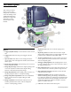
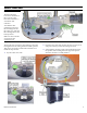
Tool Description This section provides a quick overview of the components and features of the OF 1400 EQ router. Additional information about these components and features will be discussed later in the manual. Figure 1 a. Trigger (On/Off Switch). Used to turn the router On and Off. b. Trigger Lock. This locks the power trigger in the On position. c. Speed Control. This dial is used to change the motor speed of the router. The higher the number, the faster the motor speed. i. Depth Post Lock.
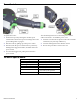
Power Controls To operate the router: 1. Set the motor speed by turning the variable speed control knob to the desired speed according to the router speed settings table on page 13. The OF 1400 EQ router has a removable power cord for added convenience. To install the power cord: 1. Insert the cord into the receptacle on the router's handle with the keyway lined up with the key. 2. Start the router by pulling up on the power switch. 2. Twist the locking knob in the direction shown. 3.
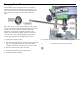
Changing Router Bits The OF1400 EQ has the unique feature of a ratcheting spindle lock. Because the spindle lock is ratcheted, you don't need to remove the wrench to make multiple turns of the collet nut; simply move the wrench back and forth. The router also has a very deep spindle bore (2¼ inches). Very few router bits are long enough to bottom out in the spindle.
Dust Collection Dust Extraction Hood The dust extraction hood can be installed on the top of the router base and connected to a vacuum for dust collection. To install the dust extraction hood, insert the mounting tabs into the router base, and turn the retaining latch to the locked position. Make sure the router bit won't cut into the extraction hood. Chip Diverter The chip diverter is used for edge forming to keep the routing debris from coming back toward the operator.
Setting the Plunge Depth Using Basic Plunge Features The basic plunge features are used for the majority of operations including both fixed depth routing and plunge routing. ► Each index number represents 0.1 mm (0.004 inch) of depth, and one full turn represents 1 mm (0.040 inch) of depth. 5. Operate the router as described in the “Basic Routing” section on page 12. 1. Unplug the router for safety. 2. Loosen the depth stop clamping lever so the depth stop is free to move up and down. 3.
Using the Depth Stop Turret The depth stop turret allows you to easily change between different depths without changing the depth stop settings. ► ► The turret posts can be calibrated for repeatable depth settings from a basepoint depth, such as making dado cuts. One of the most common tasks for the turret is making successively deeper cuts to achieve a final depth that cannot be completed in a single pass.
Using the Turret for Precision Depths This procedure is very helpful when you have day-to-day plunging operations that use the same depth relative to a basepoint. You can quickly reset the depth even after changing the router bit. Before using this procedure, make sure you perform the “Calibrating the Turret Posts” procedure on page 11 to set the difference between turret posts to the precise depth you need.
Plunge Routing Plunge routing is any operation where the router is lowered down into the cutting area after the router has been started. Most often this involves router bits that do not have a guide bearing, but can also be used for interior cutting (such as the circular cut shown on page 12). !WARNING: Take care while plunge routing to maintain control of the router at all times. For many plunge operations, one side of the router bit will be climbcutting and the other side will be push-cutting.
Advanced Routing Techniques Starting a Cut Near a Corner When routing a profile on the edge of a board, it can be difficult starting the cut at the corner without having the router lurch backward and cut into the adjoining side of the board (going past the corner). To avoid having the router catch unexpectedly, firmly hold the auxiliary handle (plunge lock knob) with one hand, and pivot the router with the main handle.
Multi-pass Cuts Nearly all routing operations can be improved by making multiple passes. In some cases the routing operation would remove too mach material to be completed safely in a single pass. In other cases, the finished cut is improved by making a shallow, clean-up pass. Depending on the type of cut being made, some multi-pass cuts are made by varying the depth and others are made by varying the position. The different types are shown below.
Pre-cutting Dovetails and Keyways Dovetail and keyway cutters are inherently weak because the upper shank of the bit is smaller than the cutting edges. If the stress on the bit is too great, the cutting tip can break. To reduce the stress on the cutter, it is common practice to plough out the majority of the material with a straight bit. The depth of the straight bit should be slightly shallower than the depth of the final bit so the bottom of the profile remains square.
Climb-cutting with Small Diameter Bits Disclaimer: Even though Festool does not condone the practice of climb-cutting with a router, the topic is known to exist in books and other written publications on router techniques. This topic is presented for information only, and is intended to warn the user of the potential dangers of climb-cutting. The information below does not explain how to perform climb-cutting, but instead, what not to do. Any user attempting climb-cutting, does so at their own risk.
Accessories Guide Rail Attachment The guide rail attachment is used to connect the router to a Festool guide rail system for making straight cuts. 3. Place the other guide block over the free end of the microadjust thumbwheel. Assembling the Guide Rail Attachment 1. Before assembling the attachment, adjust the guide rail gibs on both guide blocks. a. Place the block on one of the ribs of the guide rail. b. Tighten the two adjustment screws until the block fits snuggly to the rib but still moves freely.
6. Install and adjust the leveling outrigger to the back of the router. a. Adjust the height of the outrigger so the router is level when sitting on the edge of the guide rail. b. Tighten the clamping thumbscrew. ► The router bit radius gauge is used to indicate the location of the edge of the router bit. This is helpful for making stopped cuts. Note that this gauge indicates the radius of the bit and not the diameter. Make sure to raise the outrigger out of the way when not in use.
Alternative Method for Using the Guide Rail Attachment This procedure can be used for greater stability of the guide rail attachment, but does not permit the use of the micro-adjustment feature. This is helpful when using router bits prone to deflecting the position of the router, or when making precision cuts that must remain perfectly true to the guide rail.
Edge Guide The edge guide is used for guiding the router relative to the edge of a workpiece. This can be used for interior plunge routing (such as fluted columns) or for edge forming. While the operations are similar, there are additional setups necessary for edge form routing. Edge Forming Setup When using the edge guide for edge forming, the router bit will be within the cutout of the edge guide (as shown to the right).
Template Guides Template guides (also known as copy rings) are used to control the position of the router relative to an external pattern or template. This permits you to follow an external pattern even if the router bit does not have a guide bearing. The OF 1400 EQ router package may include either a standard Festool copy ring, a universal template guide adapter, or both. The template guide adapter allows you to use universal guides from other manufacturers with your Festool router.
Systainer (System Container) Every Festool product is shipped in its own unique system container, called a "Systainer". This provides protection and storage for the tool and accessories. All Systainers are stackable and can be interlocked together, including stacking and locking atop Festool dust extractors. Parts of the Systainer ► ► ► ► Carrying Handle. The carrying handle folds flat when not in use. Cover Latches. The two green latches on the front of the Systainer secure the cover.
Troubleshooting Symptom Motor does not start ► Possible Causes Check that the cord is properly plugged into the router and into an outlet. ► Make sure the outlet has power. Check the circuit breaker or try another outlet. ► If used with a Festool dust extractor, make sure the selector switch is pointing to "Auto". The auxiliary outlet on the dust extractor has power only when the selector is at Auto. ► Inspect the power cord (including extension cords) for damage or missing prongs.
Maintenance Routine Maintenance Any maintenance or repair work that requires opening of the motor housing should be carried out only by an authorized Customer Service Center (whose name is supplied by your dealer)! Maintenance or repair work carried out by an unauthorized person can lead to improper connection of electrical wires or other components, which can result in injury.
Changing the Motor Brushes The motor brushes wear out over time and need to be replaced by an authorized service center. Festool does not condone brush replacement by the end-user. Completion of this procedure by an unauthorized service center will void the tool's warranty. Removal Procedure CAUTION! Make sure the power cord is unplugged before beginning this procedure. 1. Remove the four screws that secure the access cover to the motor, and remove the cover. 2.
Replacement Procedure 1. Hold the carbon brush inside the brush body, and insert the brush into the mounting slot (as shown below). 2. Fully seat the brush into the slot. 3. Replace the two brush mounting screws. 4. Replace the two wire connectors to the terminals on the brushes. 5. Press the electronics module back into the router. ► ► ► Make sure the wires passing under the copper strap are not pinched by the strap. Do not force the electronics into place.