
User Manual

TROUBLESHOOTING AND CUSTOMER SUPPORT
Independent Verification of Functionality
Apogee SQ-512 and SQ-515 quantum sensors provide an amplified voltage output that is proportional to incident
PPFD. A quick and easy check of sensor functionality can be determined using a DC power supply and a voltmeter.
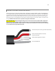
Power the sensor with a DC voltage by connecting the positive voltage signal to the red wire from the sensor and
the negative (or common) to the black wire from the sensor. Use the voltmeter to measure across the white wire
(output signal) and black wire. Direct the sensor head toward a light source and verify the sensor provides a signal.
Increase and decrease the distance from the sensor head to the light source to verify that the signal changes
proportionally (decreasing signal with increasing distance and increasing signal with decreasing distance). Blocking
all radiation from the sensor should force the sensor signal to zero.
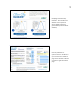
Compatible Measurement Devices (Dataloggers/Controllers/Meters)
SQ-500 series quantum sensors are calibrated with a standard calibration factor of 1.6 µmol m
-2
s
-1
per mV (SQ-
512) or 0.8 µmol m
-2
s
-1
per mV (SQ-515), yielding a sensitivity of 0.6 mV per µmol m
-2
s
-1
(SQ-512) or 1.3 mV per
µmol m
-2
s
-1
(SQ-515). Thus, a compatible measurement device (e.g., datalogger or controller) should have
resolution of at least 0.6 mV (SQ-512) or 1.3 mV (SQ-515) in order to provide PPFD resolution of 1 µmol m
-2
s
-1
.
An example datalogger program for Campbell Scientific dataloggers can be found on the Apogee webpage at
http://www.apogeeinstruments.com/downloads/.
Zero Offset Error
With the use of certain dataloggers it is possible for to measure a non-zero voltage (zero offset) when the sensor
output should be zero (no photons incident on diffuser). This offset can be corrected by applying the necessary
correction offset in the datalogger program. To test if a zero offset exists, connect the sensor to the datalogger in
question, cover the sensor head completely with a thick black cloth to block all photons, and allow the reading to
stabilize. If an offset exists, connect the sensor lead wires to a DC power supply and an independent measurement
instrument, such as a voltmeter, cover the sensor head completely to block all photons, and allow the reading to
stabilize. If the offset still exists, contact Apogee customer support to recalibrate the sensor. If the offset does not
exist, program the datalogger to take into account the offset attributed by the datalogger in question.
Cable Length
When the sensor is connected to a measurement device with high input impedance, sensor output signals are not
changed by shortening the cable or splicing on additional cable in the field. Tests have shown that if the input
impedance of the measurements device is greater than 1 mega-ohm there is negligible effect on the calibration,
even after adding up to 100 m of cable. All Apogee sensors use shielded, twisted pair cable to minimize
electromagnetic interference. For best measurements, the shield wire must be connected to an earth ground. This
is particularly important when using the sensor with long lead lengths in electromagnetically noisy environments.
Modifying Cable Length
See Apogee webpage for details on how to extend sensor cable length:
(http://www.apogeeinstruments.com/how-to-make-a-weatherproof-cable-splice/).