
Installation Guide


www.fhiaba.com · www.thevettagroup.com · Info Line 1-855-4-FHIABA (1-855-434-4222) www.fhiaba.com · www.thevettagroup.com · Info Line 1-855-4-FHIABA (1-855-434-4222)
42
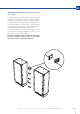
6. INSTALLATION: BOTTOM COMPRESSOR MODELS
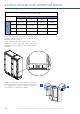
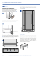
Distance between units (A+B)
C
A
18” 24” 30” 36”
B
18” 7/8” (22 mm) 15/16” (23.5 mm) 1” (24.5 mm) 1” (25.5 mm)
24” 15/16” (23.5 mm) 1” (25 mm) 1” (26 mm) 1 1/16” (27 mm)
30” 1” (24.5 mm) 1” (26 mm) 1 1/16” (27 mm) 1 1/8” (28 mm)
36” 1” (25.5 mm) 1 1/16” (27 mm) 1 1/8” (28 mm) 1 1/8” (29 mm)
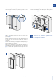
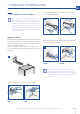
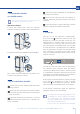
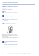
Once the appliances have been adjusted and
properly levelled, loosen the two screws holding
the sealing plate in position.
Lower the plate until flush with the floor, and re-
tighten the screws. This will ensure optimized
airflow through the condenser necessary for proper
operation.
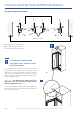
> Next join them at the front attaching the plastic
connecting brackets with the supplied screws [ 3 ].
It is suggested to use two screws for connecting
each bracket; one from each side [ 4 ].
3
4