The enclosed Warranty Information lists the services that INTRODUCTION Congratulations on selecting your new Fiat vehicle. Be Fiat offers to its customers: assured that it represents precision workmanship, dis• the Warranty Certificate with terms and conditions for tinctive styling, and high quality - all essentials that are maintaining its validity traditional to our vehicles.
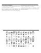
1 The detailed index at the back of this Owner’s Manual HOW TO USE THIS MANUAL Consult the Table of Contents to determine which section contains a complete listing of all subjects. contains the information you desire. Consult the following table for a description of the Since the specification of your vehicle depends on the symbols that may be used on your vehicle or throughout items of equipment ordered, certain descriptions and this Owner’s Manual: illustrations may differ from your vehicle’s equipment.
1 WARNINGS AND CAUTIONS This Owner’s Manual contains WARNINGS against operating procedures that could result in a collision or bodily injury. It also contains CAUTIONS against procedures that could result in damage to your vehicle. If you do not read this entire manual, you may miss important information. Observe all Warnings and Cautions.
1 VEHICLE IDENTIFICATION NUMBER The Vehicle Identification Number (VIN) is found on the left front corner of the instrument panel, visible through the windshield. This number also appears on the vehicle registration and title.
1 VEHICLE MODIFICATIONS/ALTERATIONS WARNING! Any modifications or alterations to this vehicle could seriously affect its roadworthiness and safety and may lead to a accident resulting in serious injury or death.
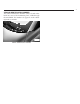
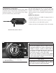
1 A WORD ABOUT YOUR KEYS The key fob contains the Remote Keyless Entry (RKE) transmitter with an integrated key (metal bladed key for mechanical backup). To use the mechanical key simply press the mechanical key release button. The authorized dealer that sold you your new vehicle has the key code numbers for your vehicle locks. These numbers can be used to order duplicate keys. Ask your authorized dealer for these numbers and keep them in a safe place. Ignition Key Removal 1.
3 Locking Doors With A Key You can insert the key with either side up. To lock the door, turn the key to the right. To unlock the door, turn the key to the left. Refer to “Body Lubrication” in “Maintaining Your Vehicle” for maintenance information. Key-In-Ignition Reminder Opening the driver’s door when the key is in the ignition and the ignition switch position is OFF/LOCK, sounds a signal to remove the key.
1 SENTRY KEYT The Sentry Keyt Immobilizer System prevents unauthorized vehicle operation by disabling the engine. The system does not need to be armed or activated. Operation is automatic, regardless of whether the vehicle is locked or unlocked. The system uses ignition keys, which have an embedded electronic chip (transponder), to prevent unauthorized vehicle operation. Therefore, only keys that are programmed to the vehicle can be used to start and operate the vehicle.
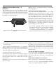
1 REMOTE KEYLESS ENTRY (RKE) — IF EQUIPPED This system allows you to lock or unlock the doors and liftgate from distances up to approximately 66 ft (20 m) using a hand-held Remote Keyless Entry (RKE) transmitter. The RKE transmitter does not need to be pointed at the vehicle to activate the system. NOTE: The line of transmission must not be blocked with metal objects.
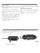
3 2. Closeness to a radio transmitter such as a radio station General Information This device complies with Part 15 of FCC rules and with tower, airport transmitter, military base, and some mobile RS-210 of Industry Canada. Operation is subject to the or CB radios. following conditions: Transmitter Battery Replacement 1. This device may not cause harmful interference. NOTE: Perchlorate Material – special handling may 2. This device must accept any interference that may be apply. See www.dtsc.ca.
5 3. Take out the battery case and remove and replace the 4. Refit the battery case inside the key and lock it by battery observing its polarity. turning the screw.
1 DOOR LOCKS The door locks can be manually locked or unlocked from inside the vehicle by using the door handle. If the door handle is pushed (red lock indicator showing) when the door is closed, the door will lock. WARNING! • Do not leave children or animals inside parked vehicles in hot weather. Interior heat build-up may cause serious injury or death. • For personal security and safety in the event of an accident, lock the vehicle doors as you drive as well as when you park and leave the vehicle.
3 Automatic Door Locks — If Equipped Automatic Door Locks Programming The doors will lock automatically on vehicles with power The Auto Close feature can be enabled or disabled with door locks if all of the following conditions are met: the Electronic Vehicle Information Center (EVIC), refer to “Electronic Vehicle Information Center (EVIC) — If 1. The Auto Lock feature is enabled. Equipped/Personal Settings (Customer-Programmable 2. All doors are closed.
1 POWER WINDOWS Power Window Switches There are single window controls located on the shifter bezel below the climate controls, which operate the driver and passenger door windows. The window controls will operate when the ignition switch is in the ON/RUN position. WARNING! Never leave children in a vehicle with the key in the ignition switch. Occupants, particularly unattended children, can become entrapped by the windows while operating the power window switches.
1 LIFTGATE To unlock the liftgate, use the Remote Keyless Entry (RKE) transmitter or by activating the power door lock switches located on the front door handles. To open the liftgate, squeeze the liftgate release handle and pull the liftgate open with one fluid motion. WARNING! • Driving with the liftgate open can allow poisonous exhaust gases into your vehicle. You and your passengers could be injured by these fumes. Keep the liftgate closed when you are operating the vehicle.
1 OCCUPANT RESTRAINTS • All seat belt systems (except the driver’s) include Some of the most important safety features in your Automatic Locking Retractors (ALRs), which lock the vehicle are the restraint systems: seat belt webbing into position by extending the belt all the way out and then adjusting the belt to the • Three-point lap and shoulder belts for all seating desired length to restrain a child seat or secure a large positions item in a seat — if equipped • Advanced Front Airbags for driver and fr
3 4. Do not lean against the door or window. Your vehicle has Supplemental Side Airbag Inflatable Curtains (SABIC) or Supplemental Seat-Mounted Side Airbags (SAB), and deployment occurs, the SABIC and SAB airbags will inflate forcefully into the space between you and the door. 5. If the airbag system in this vehicle needs to be modified to accommodate a disabled person, contact the Customer Center. Phone numbers are provided under (If You Need Assistance(.
5 WARNING! WARNING! (Continued) • It is dangerous to ride in a cargo area, inside or outside of a vehicle. In an accident, people riding in these areas are more likely to be seriously injured or killed. • Do not allow people to ride in any area of your vehicle that is not equipped with seats and seat belts. • Be sure everyone in your vehicle is in a seat and using a seat belt properly. • Wearing a seat belt incorrectly is dangerous. Seat belts are designed to go around the large bones of your body.
7 WARNING! WARNING! (Continued) • A belt that is buckled into the wrong buckle will not protect you properly. The lap portion could ride too high on your body, possibly causing internal injuries. Always buckle your belt into the buckle nearest you. • A belt that is too loose will not protect you properly. In a sudden stop you could move too far forward, increasing the possibility of injury. Wear your seat belt snugly. • A belt that is worn under your arm is dangerous.
9 6. To release the belt, push the red button on the buckle. Lap/Shoulder Belt Untwisting Procedure The belt will automatically retract to its stowed position. Use the following procedure to untwist a twisted lap/ If necessary, slide the latch plate down the webbing to shoulder belt. allow the belt to retract fully. 1. Position the latch plate as close as possible to the anchor point. WARNING! A frayed or torn belt could rip apart in an accident and leave you with no protection.
11 How To Engage The Automatic Locking Mode 1. Buckle the combination lap and shoulder belt. 2. Grasp the shoulder portion and pull downward until the entire belt is extracted. 3. Allow the belt to retract. As the belt retracts, you will hear a clicking sound. This indicates the safety belt is now in the Automatic Locking Mode.
13 are fastened. In reverse gear, if the driver or front seat passenger is unbelted, the Seat Belt Reminder Light will turn on (solid) and remain on until both front seatbelts are fastened. The driver should instruct all other occupants to fasten their seatbelts. The front passenger seat BeltAlertt is not active when the front passenger seat is unoccupied. BeltAlertt may be triggered when an animal or heavy object is on the front passenger seat or when the seat is folded flat (if equipped).
15 Supplemental Restraint System (SRS) — Airbags This vehicle has Advanced Front Airbags for both the driver and front passenger as a supplement to the seat belt restraint systems. The driver’s Advanced Front Airbag is mounted in the center of the steering wheel. The passenger’s Advanced Front Airbag is mounted in the instrument panel, above the glove compartment. The words SRS AIRBAG are embossed on the airbag covers.
17 • Supplemental Driver Side Knee Airbag • Knee Impact Bolster • Driver Advanced Front Airbag • Passenger Advanced Front Airbag • Supplemental Seat-Mounted Side Airbags (SAB) • Supplemental Side Airbag Inflatable Curtains (SABIC) • Front and Side Impact Sensors • Front Seat Belt Pretensioners, Seat Belt Buckle Switch, and Seat Track Position Sensors Advanced Front Airbag Features The Advanced Front Airbag system provides output appropriate to the severity and type of collision as determined by the Occupan
19 WARNING! Supplemental Side Airbag Inflatable Curtains (SABIC) Label Location NOTE: Airbag covers may not be obvious in the interior trim; but they will open during airbag deployment. The system includes side impact sensors that are calibrated to deploy the SAB and SABIC during impacts that require airbag occupant protection. • Your vehicle is equipped with left and right SABIC, do not stack luggage or other cargo up high enough to block the location of the SABIC.
21 The Advanced Front Airbags and Supplemental Driver Side Knee Airbag will not deploy in all frontal collisions, including some that may produce substantial vehicle damage — for example, some pole collisions, truck underrides, and angle offset collisions. On the other hand, depending on the type and location of impact, Advanced Front Airbags may deploy in crashes with little vehicle front-end damage but that produce a severe initial deceleration.
23 The Advanced Front Airbag gas is vented through the Supplemental Seat-Mounted Side Airbag (SAB) vent holes in the sides of the airbag. In this way, the Inflator Units airbags do not interfere with your control of the vehicle. The Supplemental Seat-Mounted Side Airbags (SAB) are designed to activate only in certain side collisions.
25 Enhanced Accident Response System In the event of an impact causing airbag deployment, if the communication network remains intact, and the power remains intact, depending on the nature of the event the ORC will determine whether to have the Enhanced Accident Response System perform the following functions: • Cut off fuel to the engine. • Unlock the doors automatically. After the event occurs, when the system is active, the message 9Fuel Cutoff See Handbook9 is displayed.
27 NOTE: Front and/or side airbags will not deploy in all collisions. This does not mean something is wrong with the airbag system. If you do have a collision, which deploys the airbags, any or all of the following may occur: airbag inflation. These airborne particles may irritate the skin, eyes, nose, or throat. If you have skin or eye irritation, rinse the area with cool water. For nose or throat irritation, move to fresh air. If the irritation continues, see your doctor.
29 Airbag Warning Light You will want to have the airbags ready to inflate for your protection in a collision. The Airbag Warning Light monitors the internal circuits and interconnecting wiring associated with airbag system electrical components. While the airbag system is designed to be maintenance free, if any of the following occurs, have an authorized dealer service the airbag system immediately.
WARNING! In a collision, an unrestrained child, even a tiny baby, can become a projectile inside the vehicle. The force required to hold even an infant on your lap could become so great that you could not hold the child, no matter how strong you are. The child and others could be badly injured. Any child riding in your vehicle should be in a proper restraint for the child’s size.
33 NOTE: For additional information, refer to www.seatcheck.org or call 1–866–SEATCHECK. Canadian residents, should refer to Transport Canada’s website for additional information. http://www.tc.gc.ca/roadsafety/safedrivers/childsafety/ index.htm children who weigh 20 to 40 lbs (9 to 18 kg) and who are older than one year. These child seats are also held in the vehicle by the lap/shoulder belt or the LATCH child restraint anchorage system.
35 vehicle’s seat belt for the outboard position. If your child restraints are not LATCH-compatible, you can only install the child restraints using the vehicle’s seat belts. Please refer to “Installing the Child Restraint System” for typical installation instructions. WARNING! You should never install LATCH-compatible child seats so that two seats share a common anchorage.
37 restraint rearward and downward into the seat, removing slack in the straps according to the child restraint manufacturer’s instructions. NOTE: • Ensure that the tether strap does not slip into the opening between the seatbacks as you remove the slack in the strap. • When using the LATCH attaching system to install a child restraint, please ensure that all seat belts not being used for occupant restraints are stowed and out of reach of children.
39 To attach a child restraint tether strap: • If necessary, move the seat forward to provide better access to the tether anchor. • Route the tether strap to provide the most direct path for the strap between the anchor and the child seat, • Attach the tether strap hook of the child restraint to the routing it under the head restraint. tether anchor and remove slack in the tether strap according to the child restraint manufacturer’s instructions.
1 The engine oil installed in the engine at the factory is a ENGINE BREAK-IN RECOMMENDATIONS A long break-in period is not required for the engine and high-quality energy conserving type lubricant. Oil changes should be consistent with anticipated climate drivetrain (transmission and axle) in your vehicle. conditions under which vehicle operations will occur. For Drive moderately during the first 300 miles (500 km).
1 SAFETY TIPS WARNING! (Continued) Transporting Passengers NEVER TRANSPORT PASSENGERS IN THE CARGO AREA. WARNING! • Do not leave children or animals inside parked vehicles in hot weather. Interior heat build-up may cause serious injury or death. • It is extremely dangerous to ride in a cargo area, inside or outside of a vehicle. In a collision, people riding in these areas are more likely to be seriously injured or killed.
3 authorized dealer. If the light stays on, flickers, or comes on while driving, have the system checked by an authorized dealer. Defroster Check operation by selecting the defrost mode and place the blower control on high speed. You should be able to feel the air directed against the windshield. See your authorized dealer for service if your defroster is inoperable. Floor Mat Safety Information Always use floor mats designed to fit the foot well of your vehicle.
5 Door Latches Check for positive closing, latching, and locking. Fluid Leaks Check area under vehicle after overnight parking for fuel, engine coolant, oil, or other fluid leaks. Also, if gasoline fumes are detected or if fuel, power steering fluid, or brake fluid leaks are suspected, the cause should be located and corrected immediately.
1 MIRRORS Inside Day/Night Mirror The mirror can be adjusted up, down, left, and right for various drivers. The mirror should be adjusted to center on the view through the rear window. Headlight glare from vehicles behind you can be reduced by moving the small control under the mirror to the night position (toward the rear of the vehicle). The mirror should be adjusted while set in the day position (toward the windshield).
3 The power mirror controls consist of mirror select switch Power Mirrors The power mirror controls are located on the driver’s and a four-way mirror control switch. To adjust a mirror, door trim panel. press the mirror select switch to either the L (left) or R (right) to select the mirror you need to adjust. Using the mirror control switch, press on any of the four arrows for the direction that you want the mirror to move.
5 Sun Visors Courtesy Mirrors The driver and passenger sun visors are located on the The passenger side sun visor comes equipped with a headliner, near the front windshield. The sun visor can be courtesy mirror. rotated downward or up against the door glass.
1 HANDS-FREE PHONE — IF EQUIPPED to recognize your voice. This implies that the system is nearly equally performing with different persons, i.e.: the Overview voice recognition system is of the “speaker independent” Windows Mobile™-based Fiat Blue&Me™ is a personal type. telematic system enabling to use communication and entertainment applications expressly designed for use in With this system you can also play your favorite music stored on USB device and select tracks and playback the car.
3 For further details on the mobile phones supported by Blue&Me™, refer to section Blue&Me™ SUPPORTED MOBILE PHONES. list or directly pronouncing the phone number, to answer a call and also to answer another incoming phone call. To get started with Blue&Me™ hands-free kit with voice • To interact with Blue&Me™ you can use either buttons on the steering wheel and voice commands.
5 hands-free phone, the audio output of a phone conver- Message reader functions are managed by the control buttons on the steering wheel or by the Blue&Me™ voice sation is heard through your car sound speakers. commands.
7 • To use the media player, you have to simply connect (directly or by an extension lead) your USB device to the car USB port. Turning the ignition key to ON, Blue&Me™ will start building your media library. At the end of this operation you can surf the whole library and scroll its categories as required using the buttons on the steering wheel or voice commands. Blue&Me™ will then play your selection via the car sound system.
1 SEATS Seats are a part of the Occupant Restraint System of the vehicle. WARNING! • It is dangerous to ride in a cargo area, inside or outside of a vehicle. In a collision, people riding in these areas are more likely to be seriously injured or killed. • Do not allow people to ride in any area of your vehicle that is not equipped with seats and seat belts. In a collision, people riding in these areas are more likely to be seriously injured or killed.
3 Seat Height Adjustment The driver’s seat height can be raised or lowered by using a lever, located on the outboard side of the seat. Pump the lever upward to raise the seat height, or pump the lever downward to lower the seat height. EZ Entry Feature The driver and front passenger seats have an EZ entry feature for rear seat passengers.
5 NOTE: The head restraints should only be removed by qualified technicians, for service purposes only. If either of the head restraints require removal, see your authorized dealer. WARNING! Do not place items over the top of the Active Head Restraint, such as coats, seat covers or portable DVD players. These items may interfere with the operation of the Active Head Restraint in the event of a collision and could result in serious injury or death.
1 TO OPEN AND CLOSE THE HOOD To open the hood, two latches must be released. 1. Pull the bottom of the RED hood release lever, located on the left kick panel, rearward. Safety Latch Location Hood Release Lever Lift the hood prop rod that clips to the right side (left side when standing in front of the hood) of the engine compartment. Place the hood prop rod in the hole of hood hinge to secure the hood in the open position. 2.
1 LIGHTS Multifunction Lever The multifunction lever, located on the left side of the steering wheel, controls the operation of the headlights, headlight beam selection, passing light and turn signals. NOTE: The external lights can only be turned on with the ignition in the ON/RUN position. Headlights Rotate the end of the multifunction lever upward to the first detent for headlight operation. Headlight Operation NOTE: When the headlights are turned on, the Daytime Running Lights will be deactivated.
3 Lane Change Assist Tap the lever up or down once, without moving beyond the detent, and the turn signal (right or left) will flash three times then automatically turn off. Follow Me Home/Headlight Delay When this feature is selected the driver can choose to have the headlights remain on for a preset period of time. Activation Remove the key or turn the ignition to the OFF/LOCK position, and pull the multifunction lever toward the steering wheel, within two minutes.
5 Interior Light Timing (Off Position) There are two modes of operation in this position: • When all doors are closed, a three minute timer is activated. NOTE: The timer is deactivated when the key is moved into the ON/RUN position. • When the doors are locked (either with the Key Fob or with the key in the driver’s door), the lights will turn off.
1 WINDSHIELD WIPERS AND WASHERS The windshield wiper/washer lever is located on the right side of the steering column. NOTE: The windshield wipers/washers will only operate with the ignition in the ON/RUN position. Front Windshield Wiper Operation There are five different modes of operation for the front windshield wipers.
3 from a passing vehicle. This operation will continue until REVERSE, the rear wiper will automatically operate at the lever is released. When the lever is released, the Low Speed and return to normal operation when the wipers will return to the off position and automatically transmission is shifted out of REVERSE. shut off. Front Windshield Washer Operation Pull the windshield wiper/washer lever toward the steering wheel to activate the washers and a single wipe of the windshield.
1 TILT STEERING COLUMN — IF EQUIPPED This feature allows you to tilt the steering column upward or downward. The tilt control lever is located on the left-side of the steering column, below the turn signal controls. Push down on the lever to unlock the column. With one hand firmly on the steering wheel, move the steering column up or down as desired. Push the lever up to lock the column firmly in place. WARNING! Do not adjust the steering column while driving.
1 ELECTRONIC SPEED CONTROL When engaged, the Electronic Speed Control takes over accelerator operations at speeds greater than 25 mph (40 km/h). NOTE: In order to ensure proper operation, the Electronic Speed Control system has been designed to shut down if multiple Speed Control functions are operated at the same time.
3 Pressing the RES (+) button once will result in a 1 mph Using Electronic Speed Control On Hills (2 km/h) increase in set speed. Each subsequent tap of The transmission may downshift on hills to maintain the vehicle set speed. the button results in an increase of 1 mph (2 km/h). To decrease speed while the Electronic Speed Control is set, push the SET (-) button. If the button is continually held in the SET (-) position, the set speed will continue to decrease until the button is released.
1 REAR PARK ASSIST — IF EQUIPPED The Rear Park Assist system provides an audible indication of the distance between the rear fascia/bumper and a detected obstacle when backing up, e.g. during a parking maneuver. Refer to the “Park Assist System Usage Precautions” for the limitations of this system and recommendations. corners of the rear fascia/bumper, depending on the location, type and orientation of the obstacle.
3 While audible signals are emitted, the audio system is not The sensors and wiring are tested continuously when the ignition is in the ON/RUN position. Failures are indimuted. cated immediately if they occur when the system is ON. The audible signal is cut out immediately if the distance increases. The tone cycle remains constant if the distance Even if the system is able to identify that a specific sensor measured by the inner sensors is constant.
5 WARNING! WARNING! (Continued) • Drivers must be careful when backing up even when using the Rear Park Assist system. Always check carefully behind your vehicle, look behind you, and be sure to check for pedestrians, animals, other vehicles, obstructions, and blind spots before backing up. You are responsible for safety and must continue to pay attention to your surroundings. Failure to do so can result in serious injury or death.
1 POWER SUNROOF — IF EQUIPPED The power sunroof roof switch is located in the overhead console. Power Sunroof Switch WARNING! • Never leave children in a vehicle with the key in the ignition switch. Occupants, particularly unattended children, can become entrapped by the power sunroof while operating the power sunroof switch. Such entrapment may result in serious injury or death. • In a collision, there is a greater risk of being thrown from a vehicle with an open sunroof.
3 Sun Shade — If Equipped For vehicles equipped with either a power sunroof or a fixed glass roof, there is a sun shade that can be open or closed. To open the sun shade press the tab and move the shade to a full open position.
1 ELECTRICAL POWER OUTLETS There is a standard 12 Volt (13 Amp) power outlet, located in the floor console, for added convenience. This power outlet can power mobile phones, electronics and other low power devices. Power is available when the ignition switch is in the ON/RUN or START position. Insert the cigar lighter or accessory plug into the outlet for use. To preserve the heating element, do not hold the lighter in the heating position.
3 CAUTION! • Many accessories that can be plugged in draw power from the vehicle’s battery, even when not in use (i.e., cellular phones, etc.). Eventually, if plugged in long enough, the vehicle’s battery will discharge sufficiently to degrade battery life and/or prevent the engine from starting. • Accessories that draw higher power (i.e., coolers, vacuum cleaners, lights, etc.) will degrade the battery even more quickly. Only use these intermittently and with great caution.
1 CIGAR LIGHTER — IF EQUIPPED WARNING! When the cigar lighter is in use it becomes very hot. To avoid serious injury, handle the cigar lighter with care. Always check that the cigar lighter has turned off.
1 For rear passengers, there are cupholders located on the CUPHOLDERS For the driver and front passenger, cupholders are lo- floor between the front driver and passenger seats. cated on the floor console between the front seats.
1 STORAGE Passenger Seat Storage — If Equipped Some models may be equipped with storage under the Glove Box Compartment front passenger seat. Pull outward on the latch to open The glove box is located on the right side of the instruthe storage compartment. ment panel. Pull outward on the door latch to open the glove box. Push the glove box door upward to close it.
1 CARGO AREA FEATURES The rear seatbacks have a fold down feature to allow increased cargo capacity. Push down the release button, located at the outboard top of the seatback and move the seatback to its foldeddown position to provide a flat load floor cargo area. When returning the seatback to its upright position, push rearward until the seatback is properly latched.
1 REAR WINDOW FEATURES CAUTION! (Continued) Rear Window Defroster The rear window defroster button is located in the center of the instrument panel, below the radio. Press this button to turn on the rear window defroster. An indicator in the button will illuminate when the rear window defroster is on. The rear window defroster automatically turns off after approximately 20 minutes. To manually shut the defroster off, push the button a second time.
1 INSTRUMENT PANEL FEATURES 1 2 3 4 5 6 — — — — — — Side Vent Multifunction Lever – Light Control Instrument Cluster And Warning Lights Windshield Wiper, Washer, Trip Computer Central Air Vents Storage Compartment/Radio 7 — Passenger Air Bag 8 — Glove Compartment 9 — Rear Defrost Button 10 — Hazard Button 11 — Climate Controls/Storage Compartment 12 — Power Windows Control 13 14 15 16 — — — — Storage Compartment Shift Lever Sport Button Horn/Driver Airbag
1 INSTRUMENT CLUSTER
1 INSTRUMENT CLUSTER DESCRIPTIONS 2. Rear Defrost Button Press and release this button to turn on the rear 1. Glow Plug Light — If Equipped window defroster. This indicator will illuminate The Glow Plug light will flash during engine oil when the rear window defroster is on. The rear window viscosity sensor measurement in cold weather. defroster automatically turns off after 10 minutes. During this measurement (up to 10 seconds), the starter will be disabled.
3 9. Airbag Warning Light This light will turn on for four seconds as a bulb check when the ignition switch is first turned to ON/RUN. If the light is either not on during starting, stays on, or turns on while driving, then have the system inspected at an authorized dealer as soon as possible. Refer to “Occupant Restraints” in “Things To Know Before Starting Your Vehicle” for further information. Reminder Light will illuminate and the chime will sound.
5 Accordingly, when the low tire pressure telltale illuminates, you should stop and check your tires as soon as possible, and inflate them to the proper pressure. Driving on a significantly under-inflated tire causes the tire to overheat and can lead to tire failure. Under-inflation also reduces fuel efficiency and tire tread life, and may affect the vehicle’s handling and stopping ability.
7 Certain conditions such as a loose or missing gas cap, poor fuel quality, etc., may illuminate the MIL after engine start. The vehicle should be serviced if the light stays on through several of your typical driving cycles. In most situations, the vehicle will drive normally and will not require towing. CAUTION! Prolonged driving with the MIL on could cause damage to the engine control system. It also could affect fuel economy and drivability.
9 Vehicles equipped with the Anti-Lock Brake System 21. Electronic Stability Control (ESC) OFF Indicator (ABS), are also equipped with Electronic Brake Force Light — If Equipped This light indicates the Electronic Stability ConDistribution (EBD). In the event of an EBD failure, the trol system (ESC) has been turned off by the Brake Warning Light will turn on along with the ABS driver. Light. Immediate repair to the ABS system is required. Operation of the Brake Warning Light can be checked by 22.
11 26. Temperature Gauge The temperature digital scale shows engine coolant temperature. Any reading within the normal range indicates that the engine cooling system is operating satisfactorily. The gauge pointer will likely indicate a higher temperature when driving in hot weather, up mountain grades, or when towing a trailer. It should not be allowed to exceed the upper limits of the normal operating range. CAUTION! Driving with a hot engine cooling system could damage your vehicle.
1 ELECTRONIC VEHICLE INFORMATION CENTER • System Status (EVIC) • Vehicle Information Warning Message Displays The Electronic Vehicle Information Center (EVIC) features a driver-interactive display that is located in the • Personal Settings (Customer-Programmable Features) instrument cluster. • Outside Temperature Display • Trip Computer Functions EVIC Control Buttons Press the MENU ESC button briefly to access the menu and/or go to next screen or to confirm the required menu option.
3 • Button Volume • Hill Start • Daylights (D.R.L.
5 NOTE: “Trip B” functions may be excluded (see “Trip B Trip Functions Both trip functions are resettable (reset — start of new on”). “Range” and “Instantaneous consumption” cannot trip). be reset. “Trip A” can be used to display the figures relating to: Values Displayed • Trip distance A Range This indicates the distance which may be travelled with the fuel in the tank assuming that driving conditions will not change.
7 concerning the “Trip A” makes it possible to reset only Personal Settings (Customer-Programmable the information associated with this function. Features) • The reset operation in the presence of the screens Dimmer concerning the “Trip B” makes it possible to reset only The EVIC display is provided with a light sensor capable of detecting environmental light conditions and adjustthe information associated with this function. ing the brightness of the instruments accordingly.
9 • Briefly press the MENU ESC button to go back to the Set Time (Clock) menu screen or press and hold the MENU ESC button This function may be used to set the clock through two (approximately one seconds) to go back to the main sub-menu items: “Time” and “Mode”. screen without storing settings.
11 • Briefly press the MENU ESC button “day” will flash • CD audio, CD MP3: track number; on the display; To activate (On) or to deactivate (Off) sound system info displaying proceed as follows: • Press the + or – button for setting. NOTE: The setting will increase or decrease by one unit • Briefly press the MENU ESC button (On) or (Off) will flash on the display (according to previous setting); each time the + or – button is pressed.
13 If the distance unit set is “mi” the fuel economy unit will or press and hold the MENU ESC button (approximately be displayed in “mpg”. one seconds) to go back to the main screen without storing settings. If the distance unit set is “km” the fuel economy unit will • Press and hold the MENU ESC button to go back to be displayed in km/l or l/100km. the main screen or main menu.
15 Proceed as follows to switch this function on or off: Hill Start Assist This function is used when starting a vehicle from a stop • Briefly press the MENU ESC button to display the on a hill by maintaining the same level of brake pressure three sub-menus; the driver applied for a short period of time after the foot • Briefly press the MENU ESC button (On) or (Off) will has been removed from the brake pedal.
1 SALES CODE (RAB) RADIO The instructions for use are given below and we recommend you to read them carefully. Suggestions Road Safety Please, learn how to use all different radio functions (e.g. store stations) before beginning to drive. Reception Conditions Reception conditions change constantly while driving. Reception may be interfered with by the presence of mountains, buildings or bridges, or when you are far away from the broadcaster.
3 player cannot be guaranteed to play all protected discs. The fact that the CD is protected from being copied is often shown in very small letters or is difficult to read on the actual CD cover where it may be, for example, “COPY CONTROL”, “COPY PROTECTED”, “THIS CD CANNOT BE PLAYED ON A PC/MAC”. • two 100 mm diameter full range speakers, one speaker in each of the rear side panels; • antenna on the car roof; • radio with CD /MP3 player.
5 MENU +Vol/–Vol available) in CD, Media Player and Satellite (if so equipped) Toggles RDS information in FM Advanced func- Menu activation: tions adjustment short button press Adjustment type selection: buttons or press Adjustment of values: or buttons Volume adjustment Button + press: volume increase Button – press: volume decrease CD FUNCTIONS CD ejection MODE BUTTON 12345 RADIO FUNCMODE TIONS Radio Station Search: Automatic search: buttons or • Automatic Search press (long • Manual Search press
7 • CD Display function: display of track number and on • Fast forward/rewind through tracks; mp3 discs (song title, artist) and time elapsed since • MP3 Display function: display of folder name, ID3start of the track; TAG information, (time elapsed since the start of the • Audio CD, CD-R and CD-RW playing. track, name of the file); • Playing audio or data CD, CD-R and CD-RW. WARNING! On multimedia CDs, besides audio tracks, there are data tracks too.
9 wording “TUNER Mute” will be shown on the display Use the buttons or to scroll through the Menu (in radio mode) or “CD Pause” (in CD mode). functions. To change the setting of the selected function, or buttons. Press the button again to deactivate the MUTE use the function. The volume will gradually increase until it The current status of the selected function appears on the reaches the previously set level. display.
11 • press the button to increase the sound coming Preset/User*/Classic/Rock/Jazz Functions — If button to increase Equipped from the rear speakers or the The built-in equalizer can be activated/deactivated. the sound coming from the front speakers. When the equalizer function is off, the audio settings can or buttons briefly, the levels only be changed by adjusting the “Bass” and “Treble” By pressing the will change progressively.
13 • System Reset • Speed Volume • On Volume Limit Press the MENU button again to exit the Menu function. Speed Volume Function — If Equipped This function automatically adapts the volume level to the speed of the car, turning up the volume when the speed increases to maintain the ratio with the noise level inside the passenger compartment. To activate/ deactivate the function, use the buttons.
15 Radio Each time the button is pressed the following bands are selected cyclically: (Tuner) Introduction When the car radio is turned on, the last function that • AM, FM or SAT (if equipped) was selected before turning it off (Radio, CD,CD MP3, Each band is highlighted by the corresponding wordings AUX) is activated. on the display. The last station selected on the respective To select the Radio function when another audio source is frequency band will be tuned into.
17 SIRIUS Satellite Radio With over 130 channels, SIRIUS Satellite Radio brings you more of what you love. Get 69 channels of 100% commercial-free music, plus all of your favorite sports, news, talk and entertainment. Hear every NFL game, every NASCAR race, college sports and more.
19 Sirius Subscription Issues When Replacing A Sirius Radio When a radio needs to be replaced, the dealer will need the Sirius information to order a new radio (even if the Sirius subscription has lapsed). The ESN number contains 12 digits. CD Player Introduction This chapter describes the variants regarding the operation of the CD player only: as far as the operation of the radio is concerned, refer to the description in the “Functions and Adjustments” chapter.
21 A CD which cannot be read will not be ejected until these beginning. In this case, if you want to play the previous button twice consecutively. functions are over. At the end, with the CD mode track, press the activated, the display will show the wording “CD Disc error” for a few seconds and then the CD will be ejected.
23 NOTE: When the function is activated the radio may take a few seconds to start playing. While checking the disc the display will show “CD Reading”. If no MP3 files are detected, the radio will resume playing the audio session from the point where it was interrupted. Selection Of Next/Previous Folder Press the button to select a next folder or the button to select the previous folder. The display will show the number of the folder.
1 Refer to the appropriate Blue&Me™ radio User’s Manual iPodT/USB/MEDIA PLAYER CONTROL — IF for iPodt or external USB device support capability. EQUIPPED This feature allows an iPodt or external USB device to be plugged into the USB port, located in the glove compartment.
1 STEERING WHEEL AUDIO CONTROLS The remote sound system controls are located on the rear surface of the steering wheel. Reach behind the wheel to access the switches. The right-hand control is a rocker-type switch with a pushbutton in the center and controls the volume and mode of the sound system. Pressing the top of the rocker switch will increase the volume, and pressing the bottom of the rocker switch will decrease the volume.
1 NOTE: If you experience difficulty in playing a particuCD/DVD DISC MAINTENANCE To keep a CD/DVD in good condition, take the following lar disc, it may be damaged (i.e., scratched, reflective coating removed, a hair, moisture or dew on the disc) precautions: oversized, or have protection encoding. Try a known 1. Handle the disc by its edge; avoid touching the good disc before considering disc player service. surface. 2.
1 RADIO OPERATION AND MOBILE PHONES Under certain conditions, the mobile phone being on in your vehicle can cause erratic or noisy performance from your radio. This condition may be lessened or eliminated by relocating the mobile phone antenna. This condition is not harmful to the radio.
1 CLIMATE CONTROLS 1. Temperature Control The Air Conditioning and Heating System is designed to Rotate this control to regulate the temperature of the air make you comfortable in all types of weather. inside the passenger compartment. Rotating the dial left into the blue area of the scale indicates cooler temperaSingle-Zone Manual Heating and Air Conditioning tures while rotating right into the red area indicates warmer temperatures. 2.
3 • Defrost Air is directed through the windshield and side window demist outlets. Use this mode with maximum blower and temperature settings for best windshield and side window defrosting. NOTE: The air conditioning compressor operates in Mix or Defrost, even if the Air Conditioning (A/C) button is not pressed. This dehumidifies the air to help dry the windshield. To improve fuel economy, use these modes only when necessary. 5. A/C Button Press this button to engage the Air Conditioning.
5 Single-Zone Automatic Temperature Control (ATC) — If Equipped • The Automatic Temperature Control (ATC) allows the driver to select individual comfort settings. • The system provides set-and-forget operation for optimum comfort and convenience. • The system can be controlled manually, if desired. The ATC system automatically maintains the interior comfort level desired by the driver and passenger. Automatic Temperature Control (ATC) 1.
7 9. Blower Control Down Button • When the Auto indicator is on and the Recirculation There are 12 blower speeds, the blower speed decreases indicator is off, the Recirculation is in auto mode. If the as you press this button. Performing this function will Recirculation indicator is on, the Recirculation setting cause the ATC to switch into manual mode. is manual and Recirculation is on. Automatic Operation 10. Temperature Control Down Button Provides temperature down control. Push the button for 1.
9 are selected. This allows the front occupants to control Bi-Level Air is directed through the panel and floor outlets. the volume of air circulated in the vehicle and cancel the Press and release the Panel mode button and Floor Auto mode. mode button to enter Bi-Level mode, the indicators The operator can also select the direction of the airflow illuminate when ON. Performing this function will cause by selecting one of the following positions. the ATC to switch into manual mode.
11 Operating Tips Regular cleaning of the inside of the windows with a non-filming cleaning solution (vinegar and water works Window Fogging very well) will help prevent contaminates (cigarette Windows will fog on the inside when the humidity inside smoke, perfumes, etc.) from sticking to the windows. the vehicle is high. This often occurs in mild or cool Contaminates increase the rate of window fogging. temperatures when it’s rainy or humid.
1 STARTING PROCEDURES Automatic Transmission – If Equipped Before starting your vehicle, adjust your seat, adjust both The shift lever must be in the PARK or NEUTRAL position before you can start the engine. Apply the brakes inside and outside mirrors, and fasten your seat belts. before shifting to any driving gear. WARNING! Never leave children in the vehicle alone. Leaving unattended children in a vehicle is dangerous for a number of reasons. The child or others could be seriously or fatally injured.
3 WARNING! (Continued) CAUTION! • Do not attempt to push or tow your vehicle to get it started. Vehicles equipped with an automatic transmission cannot be started this way. Unburned fuel could enter the catalytic converter and, once the engine has started, ignite and damage the converter and vehicle. If the vehicle has a discharged battery, booster cables may be used to obtain a start from a booster battery or the battery in another vehicle. This type of start can be dangerous if done improperly.
1 MANUAL TRANSMISSION — IF EQUIPPED Five–Speed Manual Transmission WARNING! You or others could be injured if you leave the vehicle unattended without having the parking brake fully applied. The parking brake should always be applied when the driver is not in the vehicle, especially on an incline. Shift Lever Fully press the clutch pedal before you shift gears. As you release the clutch pedal, lightly press the accelerator pedal.
3 CAUTION! If you skip more than one gear while downshifting or downshift at too high a vehicle speed, you could damage the engine, transmission, or clutch. To maintain a safe speed and prolong brake life, shift down to second or first gear when descending a steep grade. When turning a corner or driving up a steep grade, downshift early so that the engine will not be overburdened.
1 AUTOMATIC TRANSMISSION — IF EQUIPPED CAUTION! Damage to the transmission may occur if the following precautions are not observed: • Shift into PARK only after the vehicle has come to a complete stop. • Shift into or out of REVERSE only after the vehicle has come to a complete stop and the engine is at idle speed. • Do not shift from REVERSE, PARK, or NEUTRAL into any forward gear when the engine is above idle speed. • Before shifting into any gear, make sure your foot is firmly on the brake pedal.
3 the parking brake when leaving the vehicle in this range. Always apply the parking brake first, and then place the shift lever in the PARK position. WARNING! • Unintended movement of a vehicle could injure those in and near the vehicle. As with all vehicles, you should never exit a vehicle while the engine is running. Before exiting a vehicle, you should always shift the vehicle into PARK, remove the key from the ignition, and apply the parking brake.
1 AUTOSTICKT — IF EQUIPPED AutoStickt is a driver-interactive feature providing manual shift control, giving you more control of the vehicle. AutoStickt allows you to maximize engine braking, eliminate undesirable upshifts and downshifts, and improve overall vehicle performance. This system can also provide you with more control during passing, city driving, cold slippery conditions, mountain driving, trailer towing, and many other situations.
1 DRIVING ON SLIPPERY SURFACES Acceleration Rapid acceleration on snow covered, wet, or other slippery surfaces may cause the front wheels to pull erratically to the right or left. This phenomenon occurs when there is a difference in the surface traction under the front (driving) wheels. WARNING! Rapid acceleration on slippery surfaces is dangerous. Unequal traction can cause sudden pulling of the front wheels. You could lose control of the vehicle and possibly have a collision.
1 DRIVING THROUGH WATER Driving through water more than a few inches/ centimeters deep will require extra caution to ensure safety and prevent damage to your vehicle. Flowing/Rising Water WARNING! Do not drive on or across a road or path where water is flowing and/or rising (as in storm run-off). Flowing water can wear away the road or path’s surface and cause your vehicle to sink into deeper water. Furthermore, flowing and/or rising water can carry your vehicle away swiftly.
1 POWER STEERING The standard power steering system will give you good vehicle response and increased ease of maneuverability in tight spaces. The system will provide mechanical steering capability if power assist is lost. If for some reason the power assist is interrupted, it will still be possible to steer your vehicle. Under these conditions, you will observe a substantial increase in steering effort, especially at very low vehicle speeds and during parking maneuvers.
1 PARKING BRAKE Before leaving the vehicle, make sure that the parking brake is fully applied. Also, be certain to leave manual transmission in REVERSE or first gear. The parking brake lever is located in the center console. To apply the parking brake, pull the lever up as firmly as possible. To release the parking brake, pull the lever up slightly, press the center button, then lower the lever completely.
1 SPORT MODE Manual Transmission – If Equipped The Sport mode increases steering feedback to the driver with slight increases in effort and throttle pedal to engine response. This driving mode is useful while driving on twisty roads where more steering precision is desired in spirited cornering. 1. To activate the Sport mode, press the “SPORT” button. SPORT Button Once activated, a “SPORT” message will be displayed in the instrument cluster. 2. Momentarily release the accelerator pedal. 3.
1 BRAKE SYSTEM In the event power assist is lost for any reason (for example, repeated brake applications with the engine off), the brakes will still function. The effort required to brake the vehicle will be significantly more than that required with the power system operating. Four-Wheel Anti-Lock Brake System (ABS) The Four-Wheel ABS is designed to aid the driver in maintaining vehicle control under adverse braking conditions.
1 ELECTRONIC BRAKE CONTROL SYSTEM Your vehicle is equipped with a advanced electronic brake control system that includes Anti-Lock Brake System (ABS), Brake Assist System (BAS), Traction Control System (TCS), Hill Start Assist (HSA), and Electronic Stability Control (ESC). All systems work together to enhance vehicle stability and control in various driving conditions and are commonly referred to as ESC.
3 HSA Activation Criteria The following criteria must be met in order for HSA to activate: • Vehicle must be stopped. • Vehicle must be on a 2.5% (manual transmission) or 7% grade or greater (automatic transmission) hill. WARNING! There may be situations on minor hills (i.e., less than 8%), with a loaded vehicle, or while pulling a trailer, when the system will not activate and slight rolling may occur. This could cause a collision with another vehicle or object.
5 mode. This mode should be used for most driving situations. ESC should only be turned to “Partial Off” for specific reasons as noted below. Partial Off This mode is entered by momentarily pressing the “ESC Off” switch. This mode is intended to be used if the vehicle is in deep snow, sand or gravel conditions and more wheel spin than ESC would normally allow is required to gain traction. ESC Off Switch (Automatic Transmission) To turn ESC on again, momentarily press the “ESC Off” switch.
7 The “ESC Activation/Malfunction Indicator Light” (lo- • Each time the ignition is turned ON, the ESC system cated in the instrument cluster) starts to flash as soon as will be ON even if it was turned off previously. the tires lose traction and the ESC system becomes active. The “ESC OFF Indicator Light” indicates the The “ESC Activation/Malfunction Indicator Light” also Electronic Stability Control (ESC) is off. flashes when TCS is active.
1 TIRE SAFETY INFORMATION Tire Markings NOTE: • P (Passenger) - Metric tire sizing is based on U.S. design standards. P-Metric tires have the letter “P” molded into the sidewall preceding the size designation. Example: P215/65R15 95H. • European-Metric tire sizing is based on European design standards. Tires designed to this standard have the tire size molded into the sidewall beginning with the section width. The letter 9P9 is absent from this tire size designation. Example: 215/65R15 96H. 1 — U.S.
3 Tire Sizing Chart EXAMPLE: Size Designation: P = Passenger car tire size based on U.S. design standards (....blank....( = Passenger car tire based on European design standards LT = Light truck tire based on U.S. design standards T or S = Temporary spare tire 31 = Overall diameter in inches (in) 215 = Section width in millimeters (mm) 65 = Aspect ratio in percent (%) — Ratio of section height to section width of tire 10.
5 Tire Identification Number (TIN) The TIN may be found on one or both sides of the tire, however, the date code may only be on one side. Tires with white sidewalls will have the full TIN, including the date code, located on the white sidewall side of the tire. Look for the TIN on the outboard side of black sidewall tires as mounted on the vehicle. If the TIN is not found on the outboard side, then you will find it on the inboard side of the tire.
7 Tire Loading And Tire Pressure Tire and Loading Information Placard Tire Placard Location NOTE: The proper cold tire inflation pressure is listed on the driver’s side B-Pillar.
9 4. The resulting figure equals the available amount of NOTE: cargo and luggage load capacity. For example, if “XXX” • The following table shows examples on how to calculate total load, cargo/luggage, and towing capacities amount equals 1,400 lbs (635 kg) and there will be five of your vehicle with varying seating configurations 150 lb (68 kg) passengers in your vehicle, the amount of and number and size of occupants.
11 WARNING! Overloading of your tires is dangerous. Overloading can cause tire failure, affect vehicle handling, and increase your stopping distance. Use tires of the recommended load capacity for your vehicle. Never overload them.
1 TIRES — GENERAL INFORMATION WARNING! (Continued) Tire Pressure Proper tire inflation pressure is essential to the safe and satisfactory operation of your vehicle. Three primary areas are affected by improper tire pressure: Safety WARNING! • Improperly inflated tires are dangerous and can cause accidents. • Under-inflation increases tire flexing and can result in over-heating and tire failure. • Over-inflation reduces a tire’s ability to cushion shock.
3 Tire pressures change by approximately 1 psi (7 kPa) per 12°F (7°C) of air temperature change. Keep this in mind when checking tire pressure inside a garage, especially in the Winter. Example: If garage temperature = 68°F (20°C) and the outside temperature = 32°F (0°C) then the cold tire inflation pressure should be increased by 3 psi (21 kPa), which equals 1 psi (7 kPa) for every 12°F (7°C) for this outside temperature condition.
5 CAUTION! WARNING! Because of the reduced ground clearance, do not take your vehicle through an automatic car wash with the compact spare installed. Damage to the vehicle may result. Fast spinning tires can be dangerous. Forces generated by excessive wheel speeds may cause tire damage or failure. A tire could explode and injure someone.
7 Replacement Tires The tires on your new vehicle provide a balance of many Tires and the spare tire should be replaced after six characteristics. They should be inspected regularly for years, regardless of the remaining tread. Failure to wear and correct cold tire inflation pressure. The manufollow this warning can result in sudden tire failure.
1 TIRE CHAINS Use only compact chains, or other traction aids that meet SAE type “Class S” specifications. Chains must be the proper size for the vehicle, as recommended by the chain manufacturer. NOTE: Do not use tire chains on a compact spare tire. CAUTION! To avoid damage to your vehicle or tires, observe the following precautions: • Use Security Chain Co. (SCC) SCC Z6 low profile or equivalent chains on 185/55R15 tires only.
1 The suggested rotation method is shown in the following TIRE ROTATION RECOMMENDATIONS The tires on the front and rear of your vehicle operate at diagram. different loads and perform different steering, driving, and braking functions. For these reasons, they wear at unequal rates and tend to develop irregular wear patterns. These effects can be reduced by timely rotation of tires. The benefits of rotation are especially worthwhile with aggressive tread designs such as those on all season type tires.
1 TIRE PRESSURE MONITORING SYSTEM (TPMS) The Tire Pressure Monitor System (TPMS) will warn the driver of a low tire pressure based on the vehicle recommended cold placard pressure. The TPMS will warn the driver of a low tire pressure if the tire pressure falls below the low-pressure warning limit for any reason, including low temperature effects, or natural pressure loss through the tire. The tire pressure will vary with temperature by about 1 psi (6.9 kPa) for every 12°F (-11°C).
3 NOTE: • Seasonal temperature changes will affect tire pressure, • The TPMS is not intended to replace normal tire care and the TPMS will monitor the actual tire pressure in and maintenance or to provide warning of a tire failure the tire. or condition. Base System • The TPMS should not be used as a tire pressure gauge This is the TPMS warning indicator located in the instrument cluster. while adjusting your tire pressure.
5 3. Snow or ice around the wheels or wheel housings. 4. Using tire chains on the vehicle. 5. Using wheels/tires not equipped with TPM sensors. 3. However, after driving the vehicle for up to 20 minutes above 15 mph (24 km/h), the Tire Pressure Monitoring Telltale Light will flash on and off for 75 seconds and then remain on solid. NOTE: Your vehicle is equipped with a compact spare 4. For each subsequent ignition key cycle, a chime will wheel and tire assembly.
1 FUEL REQUIREMENTS Your vehicle is designed to meet all emission regulations and provide satisfactory fuel economy and performance when using high-quality unleaded gasoline having an octane range of 87 to 91. The manufacturer recommends the use of 91 octane or higher for optimum performance. Reformulated Gasoline Many areas of the country require the use of cleaner burning gasoline referred to as “Reformulated Gasoline.
3 MMT In Gasoline MMT is a manganese containing metallic additive that is blended into some gasoline to increase the octane number. Gasoline blended with MMT offers no performance advantage beyond gasoline of the same octane number without MMT. Gasoline blended with MMT have been shown to reduce spark plug life and reduce emission system performance in some vehicles. The manufacturer recommends using gasoline without MMT.
5 WARNING! (Continued) • Guard against carbon monoxide with proper maintenance. Have the exhaust system inspected every time the vehicle is raised. Have any abnormal conditions repaired promptly. Until repaired, drive with all side windows fully open. • Keep the liftgate closed when driving your vehicle to prevent carbon monoxide and other poisonous exhaust gases from entering the vehicle.
1 ADDING FUEL CAUTION! Fuel Filler Cap (Gas Cap) The gas cap is located on the passenger side of the vehicle. If the gas cap is lost or damaged, be sure the replacement cap is the correct one for this vehicle. • Damage to the fuel system or emission control system could result from using an improper fuel cap (gas cap). A poorly fitting cap could let impurities into the fuel system.
1 TRAILER TOWING Trailer towing with this vehicle is not recommended.
1 RECREATIONAL TOWING (BEHIND MOTORHOME, ETC.
1 Do not use this emergency warning system when the HAZARD WARNING FLASHERS The Hazard Warning flasher switch is located on the vehicle is in motion. Use it when your vehicle is disabled instrument panel below the radio. and it is creating a safety hazard for other motorists. Press the switch to turn on the Hazard Warning flashers. When the switch is activated, all directional turn signals will flash on and off to warn oncoming traffic of an emergency.
1 IF YOUR ENGINE OVERHEATS In any of the following situations, you can reduce the potential for overheating by taking the appropriate action. • On the highways — slow down. • In city traffic — while stopped, place the transmission in NEUTRAL, but do not increase engine idle speed. NOTE: There are steps that you can take to slow down an impending overheat condition: • If your air conditioner (A/C) is on, turn it off.
1 TIREFIT KIT — IF EQUIPPED TIREFIT Kit Components And Operation Small punctures up to 1⁄4 in (6 mm) in the tire tread can be sealed with TIREFIT. Foreign objects (e.g., screws or nails) should not be removed from the tire. TIREFIT can be used in outside temperatures down to approximately -4°F (-20°C). This kit will provide a temporary tire seal, allowing you to drive your vehicle up to 100 miles (160 km) with a maximum speed of 55 mph (88 km/h).
3 TIREFIT Usage Precautions • For optimum performance, make sure the valve stem on the wheel is free of debris before connecting the • Replace the TIREFIT Sealant Bottle (1) and Sealant TIREFIT kit. Hose (6) prior to the expiration date (printed on the bottle label) to assure optimum operation of the sys- • You can use the TIREFIT air pump to inflate bicycle tires. The kit also comes with two needles, located in tem.
5 WARNING! (Continued) WARNING! (Continued) • Take care not to allow the contents of TIREFIT to come in contact with hair, eyes, or clothing. TIREFIT is harmful if inhaled, swallowed, or absorbed through the skin. It causes skin, eye, and respiratory irritation. Flush immediately with plenty of water if there is any contact with eyes or skin. Change clothing as soon as possible, if there is any contact with clothing. • TIREFIT Sealant solution contains latex.
7 If the sealant (white fluid) does not flow within 0 – NOTE: If the Mode Select Knob (5) is on Air Mode and the pump is operating, air will dispense from the Air 10 seconds through the Sealant Hose (6): Pump Hose (7) only, not the Sealant Hose (6). 1. Press the Power Button (4) to turn Off the TIREFIT kit. Disconnect the Sealant Hose (6) from the valve stem. If the sealant (white fluid) does flow through the Make sure the valve stem is free of debris.
9 WARNING! TIREFIT is not a permanent flat tire repair. Have the tire inspected and repaired or replaced after using TIREFIT. Do not exceed 55 mph (88 km/h) until the tire is repaired or replaced. Failure to follow this warning can result in injuries that are serious or fatal to you, your passengers, and others around you. If tire pressure is less than 19 psi (1.3 Bar) , the tire is too badly damaged. Do not attempt to drive the vehicle further. Call for assistance. If the tire pressure is 19 psi (1.
1 JACKING AND TIRE CHANGING WARNING! (Continued) WARNING! • Do not attempt to change a tire on the side of the vehicle close to moving traffic. Pull far enough off the road to avoid the danger of being hit when operating the jack or changing the wheel. • Being under a jacked-up vehicle is dangerous. The vehicle could slip off the jack and fall on you. You could be crushed. Never put any part of your body under a vehicle that is on a jack. • Never start or run the engine while the vehicle is on a jack.
3 3. Pull the spare tire out from under the vehicle. Lowering/Raising Spare Tire CAUTION! The winch mechanism is designed for use with the jack wrench tool only. Use of an air wrench or other power tools is not recommended and they can damage the winch. Spare Tire 4. When the spare is clear, remove the knob or plastic molded nut by rotating it counter-clockwise. 4 Plastic Molded Nut Retainer 5.
5 WARNING! Do not attempt to change a tire on the side of the vehicle close to moving traffic, pull far enough off the road to avoid the danger of being hit when operating the jack or changing the wheel. 6. Block both the front and rear of the wheel diagonally opposite the jacking position. For example, if changing the right front tire, block the left rear wheel. NOTE: Passengers should not remain in the vehicle while the vehicle is being jacked. 2. Turn on the Hazard Warning flashers. 3.
7 CAUTION! Do not attempt to raise the vehicle by jacking on locations other than those indicated in the Jacking Instructions for this vehicle. 1. Remove the scissors jack and tool bag from under the driver’s seat. 2. Loosen, but do not remove, the wheel bolts by turning them to the left one turn while the wheel is still on the ground. NOTE: There are front and rear jacking locations on each side of the body (as indicated by the triangular lift point symbol on the sill molding).
9 WARNING! WARNING! Raising the vehicle higher than necessary can make the vehicle less stable. It could slip off the jack and hurt someone near it. Raise the vehicle only enough to remove the tire. To avoid the risk of forcing the vehicle off the jack, do not fully tighten the wheel bolts until the vehicle has been lowered. Failure to follow this warning may result in personal injury. 4. Using the swivel wrench, raise the vehicle by turning the jack screw to the right.
11 WARNING! CAUTION! A loose tire thrown forward in a collision or hard stop could injure the occupants in the vehicle. Have the deflated (flat) tire repaired or replaced immediately. The winch mechanism is designed for use with the jack wrench extension tool only. Use of air wrench or power tool may damage the winch. 11. Check the spare tire pressure as soon as possible. Correct the tire pressure as required. Spare Tire Stowage Reverse instructions of the spare removal section.
1 JUMP-STARTING PROCEDURE If your vehicle has a discharged battery, it can be jumpstarted using a set of jumper cables and a battery in another vehicle or by using a portable battery booster pack. Jump-starting can be dangerous if done improperly so please follow the procedures in this section carefully.
3 3. If using another vehicle to jump-start the battery, park the vehicle within the jumper cables reach, set the parking brake and make sure the ignition is OFF. WARNING! Do not allow vehicles to touch each other as this could establish a ground connection and personal injury could result. Jump-Starting Procedure WARNING! Failure to follow this procedure could result in personal injury or property damage due to battery explosion.
1 FREEING A STUCK VEHICLE NOTE: If your vehicle is equipped with Traction ConIf your vehicle becomes stuck in mud, sand or snow, it trol or Electronic Stability Control (ESC), turn the system can often be moved by a rocking motion. Turn your OFF before attempting to “rock” the vehicle. steering wheel right and left to clear the area around the CAUTION! front wheels. Then shift back and forth between DRIVE/ 1st gear and REVERSE.
1 TOWING A DISABLED VEHICLE With Ignition Key • Vehicle can be towed on a flatbed truck (all wheels off the ground). All Transmissions If it is necessary to use the accessories while being towed • Vehicle can be towed with the front wheels elevated. (wipers, defrosters, etc.), the key must be in the ON/ RUN position. Make certain the transmission remains in • Vehicle can be towed on a flatbed truck (all wheels off NEUTRAL. the ground).
1 ENHANCED ACCIDENT RESPONSE SYSTEM In the event of an impact causing airbag deployment, if the communication network remains intact, and the power remains intact, depending on the nature of the event the ORC will determine whether to have the Enhanced Accident Response System perform the following functions: • Cut off fuel to the engine. • Flash hazard lights as long as the battery has power or until the ignition key is turned off.
1 SHIFT LEVER OVERRIDE If a malfunction occurs and the shift lever cannot be moved out of the PARK position, you can use the following procedure to temporarily move the shift lever: 1. Firmly set the parking brake. 2. Remove the shift lever override access cover located on the right side of the shift lever housing. Shift Lever Override Access Cover 3. Turn the ignition switch to the ON/RUN position without starting the engine. 4. Press and maintain firm pressure on the brake pedal. 5.
1 ENGINE COMPARTMENT — 1.
1 EMISSIONS INSPECTION AND MAINTENANCE PROGRAMS In some localities, it may be a legal requirement to pass an inspection of your vehicle’s emissions control system. Failure to pass could prevent vehicle registration. For states that require an Inspection and Maintenance (I/M), this check verifies the “Malfunction Indicator Light (MIL)” is functioning and is not on when the engine is running, and that the OBD II system is ready for testing.
1 REPLACEMENT PARTS Use of genuine MOPARt parts for normal/scheduled maintenance and repairs is highly recommended to ensure the designed performance. Damage or failures caused by the use of non-MOPARt parts for maintenance and repairs will not be covered by the manufacturer’s warranty.
1 DEALER SERVICE Your authorized dealer has the qualified service personnel, special tools, and equipment to perform all service operations in an expert manner. Service Manuals are available which include detailed service information for your vehicle. Refer to these Service Manuals before attempting any procedure yourself. NOTE: Intentional tampering with emissions control systems may void your warranty and could result in civil penalties being assessed against you.
1 MAINTENANCE PROCEDURES The pages that follow contain the required maintenance services determined by the engineers who designed your vehicle. Besides those maintenance items specified in the fixed maintenance schedule, there are other components which may require servicing or replacement in the future. CAUTION! • Failure to properly maintain your vehicle or perform repairs and service when necessary could result in more costly repairs, damage to other components or negatively impact vehicle performance.
3 Engine Oil Selection For best performance and maximum protection for all engines under all types of operating conditions, the manufacturer recommends engine oils that are API Certified and meet the requirements of Chrysler Material Standard MS-6395. American Petroleum Institute (API) Engine Oil Identification Symbol This symbol means that the oil has been certified by the American Petroleum Institute (API). The manufacturer only recommends API Certified engine oils.
5 WARNING! The air induction system (air cleaner, hoses, etc) can provide a measure of protection in the case of engine backfire. Do not remove the air induction system (air cleaner, hoses, etc.) unless such removal is necessary for repair or maintenance. Make sure that no one is near the engine compartment before starting the vehicle with the air induction system (air cleaner, hoses, etc.) removed. Failure to do so can result in serious personal injury.
7 Air Conditioner Maintenance For best possible performance, your air conditioner should be checked and serviced by an authorized dealer at the start of each warm season. This service should include cleaning of the condenser fins and a performance test. Drive belt tension should also be checked at this time. CAUTION! Do not use chemical flushes in your air conditioning system as the chemicals can damage your air conditioning components. Such damage is not covered by the New Vehicle Limited Warranty.
9 from a dry windshield. Avoid using the wiper blades to remove frost or ice from the windshield. Make sure that they are not frozen to the glass before turning them on to avoid damaging the blade. Keep the blade rubber out of contact with petroleum products such as engine oil, gasoline, etc. NOTE: Life expectancy of wiper blades varies depending on geographical area and frequency of use. Poor performance of blades may be present with chattering, marks, water lines or wet spots.
11 Exhaust System The best protection against carbon monoxide entry into the vehicle body is a properly maintained engine exhaust system. If you notice a change in the sound of the exhaust system; or if the exhaust fumes can be detected inside the vehicle; or when the underside or rear of the vehicle is damaged; have an authorized technician inspect the complete exhaust system and adjacent body areas for broken, damaged, deteriorated, or mispositioned parts.
13 To minimize the possibility of catalytic converter dam- Cooling System age: • Do not shut off the engine or interrupt the ignition, when the transmission is in gear and the vehicle is in motion. • Do not try to start the engine by pushing or towing the vehicle. • Do not idle the engine with any spark plug wires disconnected or removed, such as when diagnostic testing, or for prolonged periods during very rough idle or malfunctioning operating conditions.
15 CAUTION! (Continued) • Do not use water alone or alcohol based engine coolant (antifreeze) products. Do not use additional rust inhibitors or antirust products, as they may not be compatible with the radiator engine coolant and may plug the radiator. • This vehicle has not been designed for use with Propylene Glycol based engine coolant (antifreeze). Use of Propylene Glycol based engine coolant (antifreeze) is not recommended.
17 Disposal Of Used Engine Coolant Used ethylene glycol-based engine coolant (antifreeze) is a regulated substance requiring proper disposal. Check with your local authorities to determine the disposal rules for your community. To prevent ingestion by animals or children do not store ethylene glycol-based engine coolant (antifreeze) in open containers or allow it to remain in puddles on the ground. If ingested by a child or pet, seek emergency assistance immediately. Clean up any ground spills immediately.
19 when the pads are replaced. However, low fluid level may be caused by a leak and a checkup may be needed. WARNING! Riding the brakes can lead to brake failure and possibly a collision. Driving with your foot resting or riding on the brake pedal can result in abnormally high brake temperatures, excessive lining wear, and possible brake damage. Riding the brakes may also reduce braking capacity in an emergency.
21 WARNING! (Continued) • Do not allow petroleum based fluid to contaminate the brake fluid. Brake seal components could be damaged, causing partial or complete brake failure. This could result in a collision. CAUTION! Use of improper brake fluids will affect overall clutch system performance. Improper brake fluids may damage the clutch system resulting in loss of clutch function and the ability to shift the transmission.
23 hot or cold weather and other extreme conditions will Fluid Level Check The automatic transmission has no dipstick and is dealer have an adverse effect on paint, metal trim, and underbody protection. serviced only. The following maintenance recommendations will enable Fluid and Filter Changes Refer to the “Maintenance Schedule” for the proper you to obtain maximum benefit from the corrosion resistance built into your vehicle.
25 • If you detect any stone chips or scratches in the paint, Wheel And Wheel Trim Care touch them up immediately. The cost of such repairs is All wheels and wheel trim, especially aluminum and chrome-plated wheels, should be cleaned regularly with considered the responsibility of the owner. a mild soap and water to prevent corrosion.
27 Cleaning Headlights Glass Surfaces Your vehicle has plastic headlights that are lighter and All glass surfaces should be cleaned on a regular basis less susceptible to stone breakage than glass headlights. with MOPARt Glass Cleaner or any commercial household-type glass cleaner. Never use an abrasive type Plastic is not as scratch resistant as glass and, therefore, cleaner. Use caution when cleaning the inside rear windifferent lens cleaning procedures must be followed.
1 FUSES Cavity Interior Fuses The interior fuse panel is part of the Body Control Module (BCM) and is located on the driver’s side under the instrument panel. 1 Vehicle Fuse Number F12 Mini Fuse Description Right Low Beam F32 7.
3 Underhood Fuses A second fuse panel is located on the right side of the engine compartment, next to the battery. To access the fuses, press the release tabs and remove the cover. Fuse Panel The ID number of the electrical component corresponding to each fuse can be found on the back of the cover.
5 Cavity Maxi Fuse F82 F84 F85 F87 F90 Mini Fuse Blue 30 Amp Green 10 Amp Red 15 Amp Blue 5 Amp Tan 5 Amp Tan Description Sunroof/ Convertible Top Transmission Rear Defroster, Heated Mirrors Lights Heated Mirrors
1 VEHICLE STORAGE If you are leaving your vehicle dormant for more than 21 days, you may want to take these steps to protect your battery. • Disconnect the negative cable from the battery. • Anytime you store your vehicle, or keep it out of service (i.e., vacation) for two weeks or more, run the air conditioning system at idle for about five minutes in the fresh air and high blower setting.
1 REPLACEMENT BULBS NOTE: Numbers refer to commercial bulb types that can be purchased from your authorized dealer. Interior Lights Bulb Type If a bulb needs to be replaced, visit your authorized Overhead Lamp . . . . . . . . . . . . . . . . . . . . . . . . C5W dealer or refer to the applicable Service Manual. Courtesy Lamp . . . . . . . . . . . . . . . . . . . . . . . . W5W Exterior Lights Bulb Type Front Low and High Beam Headlamp. . . . . . . . . HIR2 Front Parking/Daytime Running Lamps. . . . .
1 BULB REPLACEMENT Headlamps Front Turn Signal, Parking and Daytime Running Lamps 1. Turn the steering wheel completely to the left or right. 1. Remove the plastic cap from the back of the headlamp housing. 2. Open the wheel housing access door. 2. Rotate the bulb counter-clockwise. 3. Remove the bulb and replace as needed. 4. Install the bulb and rotate clockwise to lock in place. 5. Reinstall the plastic cap. 2 3. Remove the plastic cap from the back of the lamp Front/Rear Side Marker Lamps housing.
3 Rear Tail, Stop, Backup and Turn Signal Lamps 1. Open the liftgate. 4. Remove the tail, stop, or turn signal bulbs by pushing them slightly and turning counter-clockwise. 5. Remove the backup lamp bulb by pulling straight out. 2. Remove the two screws and remove the tail lamp 6. Replace lamps as required and reinstall lamp. assembly. Center High Mounted Stop Lamp (CHMSL) 1. Remove the two guard caps and the two fastening screws. 2. Remove the center high mounted stop lamp assembly. 3.
1 FLUID CAPACITIES Fuel (Approximate) Engine Oil with Filter 1.4 Liter Engine Cooling System 1.4 Liter Engine (MOPARt Antifreeze/Engine Coolant 10 Year/152,000 Mile Formula or equivalent) — with Manual Transmission 1.4 Liter Engine (MOPARt Antifreeze/Engine Coolant 10 Year/152,000 Mile Formula or equivalent) — with Automatic Transmission U.S. 10.5 Gallons Metric 40 Liters 4 Quarts 3.8 Liters 4.6 Quarts 4.4 Liters 5.8 Quarts 5.
1 FLUIDS, LUBRICANTS, AND GENUINE PARTS Engine Component Engine Coolant Engine Oil Engine Oil Filter Spark Plugs Fuel Selection Fluid, Lubricant, or Genuine Part MOPARt Antifreeze/Coolant 10 Year/152,000 Mile Formula OAT (Organic Additive Technology) or equivalent meeting the requirements of Chrysler Material Standard MS-12106. Use API Certified SAE 5W-30 Engine Oil, meeting the requirements of Chrysler Material Standard MS-6395. Refer to your engine oil filler cap for correct SAE grade.
1 if it has been 6 months since your last oil change even MAINTENANCE SCHEDULE if the oil change indicator message is NOT illumiThe Scheduled Maintenance services listed in this nated. manual must be done at the times or mileages specified to protect your vehicle warranty and ensure the best • Change your engine oil more often if you drive your vehicle performance and reliability. More frequent mainvehicle off-road for an extended period of time.
3 8,000 Miles (13,000 km) or 6 Months Maintenance Service Schedule Included in the Maintenance Program ❏ Change the engine oil and engine oil filter. ❏ Rotate the tires, rotate at the first sign of irregular wear, even if it occurs before 8,000 miles (13 000 km). Odometer Reading Repair Order # Date Dealer Code Signature Authorized Chrysler Dealer 24,000 Miles (39,000 km) or 18 Months Maintenance Service Schedule Included in the Maintenance Program ❏ Change the engine oil and engine oil filter.
5 32,000 Miles (52,000 km) or 24 Months Maintenance Service Schedule Included in the Maintenance Program ❏ Change the engine oil and engine oil filter. ❏ Rotate the tires, rotate at the first sign of irregular wear, even if it occurs before 32,000 miles (52 000 km). ❏ Inspect exhaust system. ❏ Replace the spark plugs. ❏ Replace the engine air cleaner filter. ❏ Replace cabin filter. ❏ Clean and lube sun roof tracks. ❏ Check and adjust hand brake. ❏ Inspect brake linings. ❏ Inspect CV joints.
7 56,000 Miles (91,000 km) or 42 Months Maintenance Service Schedule 64,000 Miles (104,000 km) or 48 Months Maintenance Service Schedule ❏ Change the engine oil and engine oil filter. ❏ Rotate the tires, rotate at the first sign of irregular wear, even if it occurs before 56,000 miles (91 000 km). Odometer Reading Repair Order # Date Dealer Code Signature Authorized Chrysler Dealer ❏ Change the engine oil and engine oil filter.
9 88,000 Miles (143,000 km) or 66 Months Maintenance Service Schedule 96,000 Miles (156,000 km) or 72 Months Maintenance Service Schedule ❏ Change the engine oil and engine oil filter. ❏ Rotate the tires, rotate at the first sign of irregular wear, even if it occurs before 88,000 miles (143 000 km). Odometer Reading Repair Order # Date Dealer Code Signature Authorized Chrysler Dealer ❏ Change the engine oil and engine oil filter.
11 120,000 Miles (195,000 km) or 90 Months Maintenance Service Schedule ❏ Change the engine oil and engine oil filter. ❏ Rotate the tires, rotate at the first sign of irregular wear, even if it occurs before 120,000 miles (195 000 km). Odometer Reading Repair Order # Date Dealer Code Signature Authorized Chrysler Dealer 128,000 Miles (208,000 km) or 96 Months Maintenance Service Schedule ❏ Change the engine oil and engine oil filter.
13 152,000 Miles (247,000 km) or 114 Months Maintenance Service Schedule ❏ Change the engine oil and engine oil filter. ❏ Rotate the tires, rotate at the first sign of irregular wear, even if it occurs before 152,000 miles (247 000 km). ❏ Flush and replace engine coolant. ❏ Replace the timing belt.
1 SUGGESTIONS FOR OBTAINING SERVICE FOR YOUR VEHICLE Prepare For The Appointment If you’re having warranty work done, be sure to have the right papers with you. Take your warranty folder. All work to be performed may not be covered by the warranty. Discuss additional charges with the service manager. Keep a maintenance log of your vehicle’s service history. This can often provide a clue to the current problem. Prepare A List Make a written list of your vehicle’s problems or the specific work you want done.
1 IF YOU NEED ASSISTANCE • If an authorized dealership is unable to resolve the The manufacturer and its authorized dealers are vitally concern, you may contact the manufacturer’s customer interested in your satisfaction. We want you to be happy center. with our products and services. Any communication to the manufacturer’s customer cenWarranty service must be done by an authorized dealer.
3 We appreciate that you have made a major investment when you purchased the vehicle. An authorized dealer has also made a major investment in facilities, tools, and training to assure that you are absolutely delighted with the ownership experience. You’ll be pleased with their sincere efforts to resolve any warranty issues or related concerns.
1 WARRANTY INFORMATION See the Warranty Information Booklet, located on the DVD, for the terms and provisions of Chrysler Group LLC warranties applicable to this vehicle and market.
1 REPORTING SAFETY DEFECTS In the 50 United States and Washington, D.C. If you believe that your vehicle has a defect that could cause a crash or cause injury or death, you should immediately inform the National Highway Traffic Safety Administration (NHTSA) in addition to notifying the manufacturer. If NHTSA receives similar complaints, it may open an investigation, and if it finds that a safety defect exists in a group of vehicles, it may order a recall and remedy campaign.
1 PUBLICATION ORDER FORMS • Diagnostic Procedure Manuals To order the following manuals, you may use either the Diagnostic Procedure Manuals are filled with diawebsite or the phone numbers listed below. Visa, Masgrams, charts and detailed illustrations. These practitercard, American Express, and Discover orders are accal manuals make it easy for students and technicians cepted. If you prefer mailing your payment, please call to find and fix problems on computer-controlled vefor an order form.
1 DEPARTMENT OF TRANSPORTATION UNIFORM TIRE QUALITY GRADES The following tire grading categories were established by the National Highway Traffic Safety Administration. The specific grade rating assigned by the tire’s manufacturer in each category is shown on the sidewall of the tires on your vehicle. significantly from the norm due to variations in driving habits, service practices, and differences in road characteristics and climate.