Fiat Uno Service and Repair Manual Peter G Strasman (923-320-3Y7) Models covered Fiat Uno 45, 55, 60, 70, 1.1 and 1.4, including Turbo ie and special/limited editions 903 cc, 999 cc, 1108 cc, 1116 cc, 1299 cc, 1301 cc and 1372 cc petrol engines with manual transmissions Does not Selecta, Fiorino type vans or Diesel engine © Haynes Publishing 1996 A book in the Haynes Service and Repair Manual Series ABCDE FGHIJ KLMNO PQRST 123 All rights reserved.
Contents LIVING WITH YOUR FIAT UNO Introduction Page 0•4 Safety First! Page 0•5 General dimensions, weights and capacities Page 0•6 Roadside Repairs Jump starting Page 0•7 Jacking, towing and wheel changing Page 0•8 Identifying leaks Page 0•9 Page 0•10 Recommended Lubricants and Fluids Page 0•13 Conversion factors Page 0•14 Routine Maintenance and Servicing Maintenance schedule (also see Chapter 13)
Contents REPAIRS & OVERHAUL Engine and Associated Systems Engine (also see Chapter 13) Page 1•1 Cooling and heating systems (also see Chapter 13) Page 2•1 Fuel system (also see Chapter 13) Page 3•1 Ignition system (also see Chapter 13) Page 4•1 Clutch (also see Chapter 13) Page 5•1 Transmission (also see Chapter 13) Page 6•1 Driveshafts, hubs, roadwheels and tyres (also see Chapter 13) Page 7•1 Page 8•1 Page 9•1 Steering Page 10•1 Suspension (also see Chapter 13) Page 11•1 Pag
0•4 Introduction Introduction to the Fiat Uno The Fiat Uno is a well designed and constructed car having an excellent power-to-weight ratio. The car is very economical, but still offers good performance with excellent body interior space. Attractive features include the options available for four- or five-speeds or three- or five-door bodywork. All essential accessories, except a radio, are fitted as standard and a sunroof is optionally available.
Safety First! Working on your car can be dangerous. This page shows just some of the potential risks and hazards, with the aim of creating a safety-conscious attitude. General hazards Scalding • Don’t remove the radiator or expansion tank cap while the engine is hot. • Engine oil, automatic transmission fluid or power steering fluid may also be dangerously hot if the engine has recently been running. Burning • Beware of burns from the exhaust system and from any part of the engine.
0•6 General dimensions, weights and capacities Dimensions Overall length . . . . . . . . . . . . . . . . . . . . . . . . . . . . . . . . . . . . . . . . . . . . . Overall width . . . . . . . . . . . . . . . . . . . . . . . . . . . . . . . . . . . . . . . . . . . . . . Height . . . . . . . . . . . . . . . . . . . . . . . . . . . . . . . . . . . . . . . . . . . . . . . . . . . Wheelbase . . . . . . . . . . . . . . . . . . . . . . . . . . . . . . . . . . . . . . . . . . . . . . . . Front track . . . . . . .
Roadside Repairs Jump starting will get you out of trouble, but you must correct whatever made the battery go flat in the first place. There are three possibilities: The battery has been drained by repeated attempts to start, or by leaving the lights on. 1 The charging system is not working properly (alternator drivebelt slack or broken, alternator wiring fault or alternator itself faulty). 2 3 The battery itself is at fault (electrolyte low, or battery worn out).
0•8 Roadside Repairs Jacking, towing and wheel changing To avoid repetition, the procedure for raising the vehicle, in order to carry out work under it, is not included before each relevant operation described in this Manual. It is to be preferred, and it is certainly recommended, that the vehicle is positioned over an inspection pit or raised on a lift. Where these facilities are not available, use ramps or jack up the vehicle strictly in accordance with the following guide.
Roadside Repairs 0•9 Identifying leaks Puddles on the garage floor or drive, or obvious wetness under the bonnet or underneath the car, suggest a leak that needs investigating. It can sometimes be difficult to decide where the leak is coming from, especially if the engine bay is very dirty already. Leaking oil or fluid can also be blown rearwards by the passage of air under the car, giving a false impression of where the problem lies. Warning: Most automotive oils and fluids are poisonous.
0•10 Routine maintenance Maintenance is essential for ensuring safety and desirable for the purpose of getting the best in terms of performance and economy from the car. Over the years the need for periodic lubrication has been greatly reduced if not totally eliminated. This has unfortunately tended to lead some owners to think that because no such action is required the items either no longer exist or will last forever.
Routine maintenance 0•11 Engine compartment (air cleaner removed for clarity) on 55S model 1 2 3 4 Strut upper mounting Washer fluid reservoir Brake fluid reservoir Ignition coil 5 6 7 8 Throttle cable Carburettor Battery Timing belt cover 9 Distributor 10 Oil filler cap 11 Radiator electric cooling fan 12 13 14 15 Radiator Coolant expansion tank Front mounting Clutch operating cable
0•12 Routine maintenance View of front end from below on 55S model 1 2 3 4 5 6 7 8 9 10 11 12 13 View of rear end from below 1 2 3 4 5 6 7 8 9 10 Suspension trailing arm Fuel tank filler hose Rear axle beam Rear silencer Spring seat Expansion box Handbrake cable Fuel tank support strap Fuel tank Handbrake cable adjuster Tie-rod end Track control arm Lower mounting Gearchange control rods Exhaust pipe Driveshafts Transmission Sump drain plug Disc caliper Front mounting Horns Radiator Oil filter
Lubricants and Fluids Component or system Lubricant type/specification 1 Engine Multigrade engine oil, viscosity SAE 15W/40, meeting API-SG or CCMC G2/G3 specification (or equivalent multigrade engine oil with viscosity rating suitable for ambient temperature in which vehicle is operated see owner’s handbook) 2 Transmission: 1372 cc Turbo ie model All other models FIAT ZC 80/S gear oil FIAT ZC 90 gear oil 3 Cooling system Ethylene glycol based antifreeze 4 Brake and clutch hydraulic system(s) Hydr
0•14 Conversion Factors Length (distance) Inches (in) Feet (ft) Miles x 25.4 x 0.305 x 1.609 = Millimetres (mm) = Metres (m) = Kilometres (km) x 0.0394 = Inches (in) x 3.281 = Feet (ft) x 0.621 = Miles Volume (capacity) Cubic inches (cu in; in3) Imperial pints (Imp pt) Imperial quarts (Imp qt) Imperial quarts (Imp qt) US quarts (US qt) Imperial gallons (Imp gal) Imperial gallons (Imp gal) US gallons (US gal) x x x x x x x x 16.387 = 0.568 = 1.137 = 1.201 = 0.946 = 4.546 = 1.201 = 3.
1•1 Chapter 1 Engine For modifications, and information applicable to later models, see Supplement at end of manual Contents Part 1: General Crankcase ventilation system . . . . . . . . . . . . . . . . . . . . . . . . . . . . . . Description . . . . . . . . . . . . . . . . . . . . . . . . . . . . . . . . . . . . . . . . . . . . Engine oil and filter . . . . . . . . . . . . . . . . . . . . . . . . . . . . . . . . . . . . . . Major operations possible without removing the engine from the car . . . . . . . .
1•2 Engine – general Cylinder block and crankcase Material . . . . . . . . . . . . . . . . . . . . . . . . . . . . . . . . . . . . . . . . . . . . . . . . . . Bore diameter . . . . . . . . . . . . . . . . . . . . . . . . . . . . . . . . . . . . . . . . . . . . . Diameter of camshaft bearing bores in crankcase timing gear end: Grade B . . . . . . . . . . . . . . . . . . . . . . . . . . . . . . . . . . . . . . . . . . . . . . . . Grade C . . . . . . . . . . . . . . . . . . . . . . . . . . . . . . . . . . . .
Engine – general 1•3 Cylinder head and valves Material (cylinder head) . . . . . . . . . . . . . . . . . . . . . . . . . . . . . . . . . . . . . . Maximum distortion . . . . . . . . . . . . . . . . . . . . . . . . . . . . . . . . . . . . . . . . Valve guide bore in head . . . . . . . . . . . . . . . . . . . . . . . . . . . . . . . . . . . . Valve guide outside diameter . . . . . . . . . . . . . . . . . . . . . . . . . . . . . . . . . Valve guide oversizes . . . . . . . . . . . . . . . . . . . . . . . . . .
1•4 Engine – general 1116 cc and 1301 cc engine Type . . . . . . . . . . . . . . . . . . . . . . . . . . . . . . . . . . . . . . . . . . . . . . . . . . . . Four cylinder in-line, liquid cooled single overhead camshaft. Transversely mounted with end-on transmission General 1116 cc 1301 cc 80.0 mm (3.15 in) 86.4 mm (3.40 in) 55.5 mm (2.19 in) 55.5 mm (2.19 in) 1116 cc (68.08 cu in) 1301 cc (79.36 cu in) 9.2 : 1 9.1 : 1 40.5 kW (55 bhp) at 5600 rev/min 50 kW (68 bhp) at 5700 rev/min 86.
Engine – general 1•5 Crankshaft Journal diameter . . . . . . . . . . . . . . . . . . . . . . . . . . . . . . . . . . . . . . . . . . . Standard main bearing shell thickness . . . . . . . . . . . . . . . . . . . . . . . . . . Undersizes . . . . . . . . . . . . . . . . . . . . . . . . . . . . . . . . . . . . . . . . . . . . . . . Crankshaft endfloat . . . . . . . . . . . . . . . . . . . . . . . . . . . . . . . . . . . . . . . . Crankpin diameter . . . . . . . . . . . . . . . . . . . . . . . . . . . . . . . .
1•6 Engine – general Auxiliary shaft Bearing internal diameter (reamed): No. 1 (timing belt end) . . . . . . . . . . . . . . . . . . . . . . . . . . . . . . . . . . . . . No. 2 . . . . . . . . . . . . . . . . . . . . . . . . . . . . . . . . . . . . . . . . . . . . . . . . . . Shaft journal diameter: No. 1 (timing belt end) . . . . . . . . . . . . . . . . . . . . . . . . . . . . . . . . . . . . . No. 2 . . . . . . . . . . . . . . . . . . . . . . . . . . . . . . . . . . . . . . . . . . . . . . . . . . 35.
Engine – general 1•7 1 Fig. 1.1 Longitudinal section of 903 cc engine (Sec 1) Fig. 1.2 Cross-section of 903 cc engine (Sec 1) Fig. 1.3 Longitudinal section of 1116 cc and 1301 cc engines (Sec 1) Fig. 1.
1•8 Engine – general 2.2 Withdrawing engine oil dipstick (1116 cc) 2 Engine oil and filter 2.3A Typical dipstick markings 1 1 The engine oil level should be checked at the weekly service (see “Routine Maintenance”). Preferably check the level cold, first thing in the morning or if the engine has been running, allow at least ten minutes to elapse after switching off to permit the oil to drain.
903 cc engine 1•9 Cylinder head - removal and refitting Sump pan - removal and refitting Pistons/connecting rods - removal and refitting Oil pump - removal and refitting Engine mountings - renewal 1116 cc and 1301 cc engines Valve clearances - checking and adjusting Camshaft and camshaft carrier - removal and refitting Timing belt - removal and refitting Cylinder head - removal and refitting Sump pan - removal and refitting Oil pump - removal and refitting Pistons/connecting rods - removal and refitting En
1•10 903 cc engine 6.13A Fitting the sprockets and timing chain 6.13B Timing mark alignment 6.13C Self-tensioning links on inside of chain 13 Engage the timing chain with the teeth of the crankshaft sprocket. Then locate the camshaft sprocket within the upper loop of the chain in such a way that when the sprocket is pushed onto the camshaft, the timing marks will be in alignment. Make sure that the self-tensioning links are on the inside of the chain against the cylinder block (photos).
903 cc engine 1•11 7.20 Cylinder head gasket 7.24A Cylinder head bolt in intake manifold 19 Never smear grease on the gasket as, when the engine heats up, the grease will melt and may allow compression leaks to develop. 20 The cylinder head gasket cannot be fitted incorrectly due to its asymmetrical shape, but the word ALTO should be uppermost in any event (photo). 21 The locating dowels should be refitted to the front right and left-hand side cylinder head securing bolt holes.
1•12 903 cc engine 8.7B Sump pan nut, bolts and washers 9 Pistons/connecting rods removal and refitting 3 1 Remove the cylinder head as described in Section 7. 2 Remove the sump pan as described in Section 8. 3 Undo and remove the big-end cap retaining bolts and keep them in their respective order for correct refitting. 4 Check that the connecting rod and big-end bearing cap assemblies are correctly marked.
903 cc engine 1•13 24 Screw in the big-end bolts and tighten to the specified torque (photo). 25 Refit the sump pan (Sec 8) and the cylinder head (Sec 7). 26 Refill the engine with oil and coolant. 10 Oil pump removal and refitting 1 1 Remove the sump pan as described in Section 8. 2 Unscrew the two bolts which hold the oil pump housing to the underside of the crankcase and withdraw the pump. Remove and discard the pump flange gasket. 9.24 Tightening a big-end bolt 10.
1•14 903 cc engine Fig. 1.12 Coolant hoses at thermostat housing (Sec 13) Fig. 1.13 Coolant hose at rear of coolant pump (Sec 13) Fig. 1.14 Fuel inlet hose disconnected from pump (Sec 13) Fig. 1.15 Fuel return hose disconnected from carburettor (Sec 13) Fig. 1.16 Gearchange rods disconnected (Sec 13) Fig. 1.17 Tie-rod end balljoint disconnected (Sec 13) Fig. 1.18 Hub carrier detached from strut clamp (Sec 13) Fig. 1.
903 cc engine 1•15 31 Support the weight of the transmission and withdraw it in a straight line from the engine. 14 Engine - dismantling (general) 1 Stand the engine on a strong bench at a suitable working height. Failing this, it can be dismantled on the floor, but at least stand it on a sheet of hardboard. 2 During the dismantling process, the greatest care should be taken to keep the exposed parts free from dirt. As the engine is stripped, clean each part in a bath of paraffin.
1•16 903 cc engine Fig. 1.23 Timing cover, sump pan and oil seals (Sec 16) 1 2 3 4 5 6 7 Sump pan bolt Washer Sealing strip Side gasket Side gasket Block/crankcase Gasket 8 9 10 11 Bolt Washer Bolt and washer Crankshaft front oil seal 12 Timing cover 14 Gasket 16 Engine complete dismantling 3 1 Unbolt and remove the rocker cover. 2 Unscrew the rocker pedestal securing nuts and lift away the rocker assembly. 3 Remove the pushrods, keeping them in their original fitted order.
903 cc engine 1•17 light alloy construction and is easily damaged use a blunt scraper or rotary wire brush to clean all traces of carbon deposits from the combustion spaces and the ports. The valve head stems and valve guides should also be freed from any carbon deposits. Wash the combustion spaces and ports down with paraffin and scrape the cylinder head surface free of any foreign matter with the side of a steel rule, or a similar article.
1•18 903 cc engine Fig. 1.25 Checking a crankpin (Sec 18) Fig. 1.26 Piston/connecting rod relationship (Sec 18) used to check bore wear and taper against the Specifications, but this is a pointless operation if the engine is obviously in need of reboring due to excessive oil consumption. 5 Your engine reconditioner will be able to re-bore the block for you and supply the correct oversize pistons to give the correct running clearance.
903 cc engine 1•19 18.24B Checking piston ring end gap 18.32 Camshaft bearing clearance and end gap. Both clearances should be checked with a feeler gauge. Check the end gap when the ring has been pushed squarely down the cylinder bore for two or three inches (photos). 25 If new rings are being used and the cylinder bores have not been rebored, always make sure that the top compression ring has been stepped to prevent it contacting the bore wear ridge.
1•20 903 cc engine Oil seals and gaskets 1 2 3 4 5 6 7 8 9 10 11 Bolt Bolt Washers Washer Spring Drive gear Top housing Driven gear Plate Pressure relief valve Lower housing and oil pick-up 12 Filter screen Fig. 1.27 Exploded view of oil pump (Sec 18) 49 It is recommended that all gaskets and oil seals are renewed at major engine overhaul. Sockets are useful for removing or refitting oil seals. An arrow is moulded onto some seals to indicate the rotational direction of the component which it serves.
903 cc engine 1•21 20.6 Fitting a main bearing cap micrometer to trace the cause of the trouble. It is very seldom that any trouble of this nature will be experienced when fitting the crankshaft. 9 Tighten the main bearing bolts to the specified torque wrench settings (photo). 10 Using a dial gauge or feeler blades inserted between a thrust washer and the crankshaft, check the crankshaft endfloat. If it exceeds the specified limit, the thrust washers can be changed for thicker ones (photo).
1•22 903 cc engine 20.17 Camshaft front bearing lockscrew 17 Screw in the camshaft front bearing lockscrew (photo). Oil pump 18 Refit the oil pump as described in Section 10. Timing chain and sprockets 19 Fit the timing chain and sprockets as described in Section 6. Fit the Woodruff key to the crankshaft nose. 20 Using a new gasket, fit the timing chain cover, but leave the bolts finger tight (photo).
903 cc engine 1•23 removed and the weight of the car is again on its roadwheels. 4 Fill the cooling system. 5 Fill the engine with oil. 6 Replenish lost transmission oil. 7 Reconnect the battery. 8 Adjust the clutch pedal as described in Chapter 5. 24 Engine - initial start-up after overhaul or major repair 4 1 Make sure that the battery is fully charged and that all lubricants, coolant and fuel are replenished.
1•24 1116 cc and 1301 cc engine 27.13A Removing camshaft end cover 27.13B Withdrawing camshaft from carrier 5 In practice, if several shims have to be changed, they can often be interchanged, so avoiding the necessity of having to buy more new shims than is necessary. 6 If more than two or three valve clearances are found to be incorrect, it will be more convenient to remove the camshaft carrier for easier removal of the shims.
1116 cc and 1301 cc engine 1•25 Fig. 1.28 TDC marks (1) at front of engine (Sec 28) 28.8 Slipping timing belt onto tensioner pulley 8 Fit the new belt. Start at the crankshaft drive pulley and, taking care not to kink or strain the belt, slip it over the camshaft pulley. The camshaft may have to be turned slightly to mesh the pulley with the teeth on the belt. Fit the belt on the tensioner pulley last; if this is difficult, do not lever or force the belt on, recheck the belt (photo).
1•26 1116 cc and 1301 cc engine 29.21A Cylinder head gasket top face marking head gasket must be fitted (ALTO visible) so that the oil pressure hole in the block is central in the copper ringed cut-out in the gasket (photos). Make sure that the gasket surfaces on head and block are perfectly clean and free from oil, otherwise the heat sealing (polymerisation) process of the gasket cannot take place. 22 Tighten the cylinder head nuts and bolts to the specified torque, in the sequence shown in Fig. 1.30.
1116 cc and 1301 cc engine 1•27 32.14 Fitting piston into cylinder bore 32.15 Fitting a big-end cap 32.16 Tightening a big-end cap nut 2 The big-end bearing shells can be renewed without having to remove the cylinder head if the caps are unbolted and the piston/connecting rod pushed gently about one inch up the bore (the crankpin being at its lowest point). If these shells are worn, however, the main bearing shells will almost certainly be worn as well.
1•28 1116 cc and 1301 cc engine from the suspension struts and then remove the bolts which secure the hub carriers to the U-clamps at the base of the suspension struts. 23 Pull the tops of the hub carriers down and then outwards and push the driveshafts from them. 24 Unbolt the driveshaft inboard boot retainers and then remove the driveshafts from the transmission. 25 Support the engine on a hoist or use a trolley jack under the engine/transmission.
1116 cc and 1301 cc engine 1•29 39.4B Double valve springs 39.5 Removing a valve 6 Remove the spring seat (photo). 7 Discard the valve stem oil seal and fit a new one (photo). 8 Remove the remaining valves in a similar way and keep the components in their originally fitted sequence. 9 Reassembly is a reversal of removal.
1•30 1116 cc and 1301 cc engine 42.1 Main bearing shells 42.2 Crankshaft thrust washers 42.3 Lowering crankshaft into position blades will serve as a reasonable alternative. The difference between the two dimensions (feeler blades) or the total movement of the crankshaft (dial gauge) should be within the specified tolerance. If it is not, the thrust washers at No. 5 main bearing will have to be changed for thicker ones; this will require taking out the crankshaft again to reach them.
1116 cc and 1301 cc engine 1•31 42.10A Auxiliary shaft end plate and gasket 42.10B Tightening auxiliary shaft end plate bolt 42.11 Tightening camshaft sprocket bolt. Note sprocket locking device plate to the crankcase, using a new gasket (photos). 11 Fit the belt sprocket and partially tighten its bolt. Then, using an oil filter strap wrench or similar device to hold the sprocket against rotation, tighten the bolt to the specified torque.
1•32 1116 cc and 1301 cc engine 42.19 Tightening flywheel bolts 42.20 Fitting crankshaft timing belt sprocket 42.21 Crankshaft pulley and nut prevent the flywheel turning. Fit the engine endplate (photo). 20 Fit the timing belt sprocket to the front end of the crankshaft (photo). 21 Fit the crankshaft pulley and the nut; tighten it to the specified torque, again jamming the starter ring gear to prevent the crankshaft from rotating (photo).
1116 cc and 1301 cc engine 1•33 44.2 Lifting lug at bellhousing bolt 44.8A Raising engine/transmission into engine compartment 44.8B Left-hand engine mounting 2 Draw the engine and transmission together by screwing in the connecting bolts. Refit lifting lugs and hose and wiring clips (photo). 3 Bolt the lower cover plate to the face of the flywheel housing. 4 Bolt the starter motor into position. 5 Bolt the mounting brackets into place.
1•34 1116 cc and 1301 cc engine 44.21A Heater hose at manifold 44.21B Brake servo hose at manifold 44.22A Reversing lamp switch on transmission to the engine. Also reconnect the brake servo hose to the intake manifold (photos). 22 Reconnect the leads to the reversing lamp switch. Reconnect the transmission earth lead (photos). 23 Reconnect the clutch cable and adjust as described in Chapter 5. 24 Reconnect the speedometer drive cable to the transmission and tighten the knurled retaining ring.
All engines 1•35 Fault finding - all engines Note: When investigating starting and uneven running faults, do not be tempted into snap diagnosis. Start from the beginning of the check procedure and follow it through. It will take less time in the long run. Poor performance from an engine in terms of power and economy is not normally diagnosed quickly. In any event, the ignition and fuel systems must be checked first before assuming any further investigation needs to be made.
1•36 All engines Engine idles roughly m Mixture too weak m Air leak in carburettor m Air leak at inlet manifold to cylinder head, or inlet manifold to carburettor m Carburettor incorrectly adjusted m Other fuel system fault (see Chapter 3) m Low tension leads on coil loose m Low tension lead to distributor loose m Dirty, incorrectly set, or pitted contact breaker points m Tracking across inside of distributor cover m Faulty coil m Ignition leads loose m Spark plugs fouled or incorrectly gapped.
2•1 Chapter 2 Cooling and heating systems For modifications, and information applicable to later models, see Supplement at end of manual Contents Coolant mixtures . . . . . . . . . . . . . . . . . . . . . . . . . . . . . . . . . . . . . . . . 3 Coolant pump - removal, overhaul and refitting . . . . . . . . . . . . . . . . 9 Cooling system - draining, flushing and refilling . . . . . . . . . . . . . . . . 2 Cooling system sensors . . . . . . . . . . . . . . . . . . . . . . . . . . . . . . . . . .
2•2 Cooling and heating systems 1.5 Expansion tank cap dribble out of the hole in the heater hose. Screw in the plug. 11 Top up the expansion tank to the specified level and screw on the tank cap. 12 Start the engine and run it until the cooling fan cuts in. Switch off, allow to cool and top up if necessary to the specified mark on the expansion tank. Fig. 2.
Cooling and heating systems 2•3 4.2 Thermostat housing 4.4 Fitting thermostat housing (1116 cc engine) 7.3A Radiator top hose inhibitor should be used. Again, a reputable make giving full protection must be chosen and renewed every two years. Inhibitors with dyes are useful for finding leaks, and on some makes the dye shows when the inhibiting ability is finished. 3 To remove the switch, disconnect the leads from the terminals and unscrew the switch.
2•4 Cooling and heating systems 9.4 Coolant distribution tube at rear of pump towards the engine. Slip the belt off the pulleys. If this is difficult, turn the crankshaft pulley using a spanner on its retaining nut while pressing the belt over the edge of the pulley rim. Use this method to fit the new belt after first having engaged it with the coolant pump and alternator pulley grooves. 5 Tension the belt as previously described.
Cooling and heating systems 2•5 2 Air is drawn in through the grille at the base of the windscreen. It then passes through the coolant heated matrix when it can then be distributed through selective outlets according to the setting of the control levers. 3 A booster fan is provided for use when the car is stationary or is travelling too slowly to provide sufficient air ram effect. 4 Fresh air outlets are provided at each end and centrally on the facia panel. 9.21 Fitting coolant pump (1116 cc engine) Fig.
2•6 Cooling and heating systems 12.5 Pulling off heater control lever knob 12.6A Heater control panel screw 12.6B Removing heater control panel escutcheon upper part of the heater casing (photo). 10 Unscrew the mounting nuts which hold the heater to the bulkhead (photo). 11 Lower the heater to the floor, taking care not to allow coolant to spill on the carpet. 12 Refitting is a reversal of removal. Fill the cooling system. 12.
Cooling and heating systems 2•7 2 The control lever mounting platform can be removed after extracting its fixing screws. 3 The coolant control valve can be removed after extracting its fixing nuts. 4 Unscrew the screws which hold the heater matrix in the casing and then slide the matrix from its location. 5 If the matrix is leaking, do not attempt a repair, but obtain a new one. These are usually obtainable on an exchange basis from radiator repairers.
2•8 Cooling and heating systems Fault finding - cooling and heating systems Overheating Loss of coolant m m m m m m m m m m m m m m m m m m Insufficient coolant in system Pump ineffective due to slack drivebelt Radiator blocked either internally or externally Kinked or collapsed hose causing coolant flow restriction Thermostat not working properly Engine out of tune Ignition timing retarded or auto advance malfunction Cylinder head gasket blown Engine not yet run-in Exhaust system partially blocked Eng
3•1 Chapter 3 Fuel system For modifications, and information applicable to later models, see Supplement at end of manual Contents Accelerator cable - adjustment and renewal . . . . . . . . . . . . . . . . . . Air cleaner - servicing, removal and refitting . . . . . . . . . . . . . . . . . . . Carburettor - removal and refitting . . . . . . . . . . . . . . . . . . . . . . . . . . Carburettor idle speed and mixture - adjustment . . . . . . . . . . . . . . .
3•2 Fuel system Solex C32 DISA 11 Application . . . . . . . . . . . . . . . . . . . . . . . . . . . . . . . . . . . . . . . . . . . . . . . Venturi . . . . . . . . . . . . . . . . . . . . . . . . . . . . . . . . . . . . . . . . . . . . . . . . . . . Auxiliary venturi . . . . . . . . . . . . . . . . . . . . . . . . . . . . . . . . . . . . . . . . . . . Main jet . . . . . . . . . . . . . . . . . . . . . . . . . . . . . . . . . . . . . . . . . . . . . . . . . . Air bleed jet . . . . . . . . . . . . . . . . . .
Fuel system 3•3 Weber 32 ICEV 51/250 (continued) Fuel inlet needle valve . . . . . . . . . . . . . . . . . . . . . . . . . . . . . . . . . . . . . . Anti-syphon device. . . . . . . . . . . . . . . . . . . . . . . . . . . . . . . . . . . . . . . . . Idle mixture adjustment hole . . . . . . . . . . . . . . . . . . . . . . . . . . . . . . . . . Float setting (fuel level) . . . . . . . . . . . . . . . . . . . . . . . . . . . . . . . . . . . . . . Float setting (travel/stroke) . . . . . . . . . . . . . . . . . .
3•4 Fuel system Engine idle speed At normal operating temperature . . . . . . . . . . . . . . . . . . . . . . . . . . . . . . 800 to 850 rev/min CO percentage at idle 3.5 maximum ................................. Torque wrench settings Exhaust manifold nuts (903 cc) . . . . . . . . . . . . . . . . . . . . . . . . . . . . . . . Exhaust and intake manifold nuts (1116 cc, 1301 cc) . . . . . . . . . . . . . . Fuel pump nuts . . . . . . . . . . . . . . . . . . . . . . . . . . . . . . . . . . . . . . . . . .
Fuel system 3•5 3.4 Fuel pump 3.6A Fuel pump on mounting studs 3.6B Fuel pump spacer and pushrod 12 The air cleaner on the 1301 cc engine is mounted on the four flange studs of the carburettors, their nuts being accessible after the air cleaner lid has been removed and the filter element extracted. 13 Refitting of all types of air cleaner is a reversal of removal. spacer should always be 0.3 mm thick, but gaskets for the outboard side are available in thicknesses 0.3, 0.7 and 1.
3•6 Fuel system Fig. 3.1 Weber 32 ICEV 50/250 (Sec 6) Fig. 3.2 Solex C32 DISA 11 (Sec 6) Fig. 3.3 Weber 32 ICEV 51/250 (Sec 6) Fig. 3.4 Solex C32 DISA 12 (Sec 6) Fig. 3.5 Weber 30/32 DMTR 90/250 (Sec 6) Fig. 3.6 Weber 32 ICEE/250 (Sec 6) 6 Carburettors - general Fig. 3.7 Solex C30/32 CIC/1 (Sec 6) Fig. 3.
Fuel system 3•7 8.2 Fuel hose at carburettor 7 Carburettor idle speed and mixture - adjustment 8.6 Carburettor mounting flange nut 4 1 All carburettors have their mixture adjustment set in production. The screw is fitted with a tamperproof cap. 2 Under normal circumstances, only the idle speed screw need be adjusted to set the engine idle speed to the specified level.
3•8 Fuel system Fig. 3.12 Fast idle adjustment diagram (Weber 32 ICEV 50/250) (Sec 9) Fig. 3.13 Anti-flooding device (Weber 32 ICEV 50/250) (Sec 9) A = 0.75 to 0.80 mm (0.030 to 0.032 in) Y = 3.75 to 4.25 mm (0.148 to 0.167 in) plate should be open (dimension A) (Fig. 3.1 2) between 0.75 and 0.80 mm (0.030 and 0.032 in). Adjust if necessary by means of the screw and locknut. Anti-flooding device 11 This consists of a diaphragm capsule and link rod.
Fuel system 3•9 Fig. 3.18 Fast idle adjustment diagram (Solex C32 DISA 11) (Sec 10) Fig. 3.19 Anti-flooding device adjustment diagram (Solex C32 DISA 11) (Sec 10) X = 0.90 to 1.0 mm (0.035 to 0.039 in) X = 4.75 to 5.25 mm (0.187 to 0.207 in) pump jet and give ten full strokes of the throttle lever, pausing between each stroke to allow fuel to finish dripping. 8 The total volume of fuel collected should be between 2.5 and 4.5 cc.
3•10 Fuel system Fig. 3.22 Primary valve plate opening (Weber 30/32 DMTR 90/250) (Sec 14) Fig. 3.23 Bending throttle lever stop (Weber 30/32 DMTR 90/250) (Sec 14) X = 6.45 to 6.95 mm (0.25 to 0.27 in) X (primary) = 13.5 to 14.5 mm (0.53 to 0.57 in) Y (secondary) = 14.5 to 15.5 mm (0.57 to 0.61 in) control unit is functioning, if the tachometer does not register, renew the ignition control unit.
Fuel system 3•11 Fig. 3.28 Float setting diagram (Solex C30-32 CIC/1) (Sec 14) Fig. 3.27 Anti-flooding device (automatic) adjustment diagram (Weber 30/32 DMTR 90/250) (Sec 14) Y = 3.75 to 4.25 mm (0.148 to 0.167 in) Anti-flooding device (automatic) 10 Pull the choke control fully out and hold the control lever, on the anti-flooding device, depressed. There should be a gap (Y) (Fig. 3.27) between the edge of the choke valve plate and the carburettor wall of between 3.75 and 4.25 mm (0.15 and 0.17 in).
3•12 Fuel system 17.4 Throttle cable sleeve and bracket 17 Accelerator cable adjustment and renewal 2 1 The socket type cable end fitting is detached from the carburettor throttle lever simply by prising it off the ball stud. 2 Adjustment can be carried out by releasing the locknut and turning the end fitting. With the accelerator pedal fully depressed, check that full throttle can be obtained at the carburettor. 3 To renew the cable, prise off the end fitting from the carburettor throttle lever.
Fuel system 3•13 19.7B Exhaust tailpipe mounting 19.10 Exhaust pipe socket clamp 6 On 1116 cc and 1301 cc models, the exhaust system is of dual downpipe, two silencer, two section type. 7 The exhaust system is flexibly mounted (photo). 8 Do not attempt to separate the sections of the exhaust system, while in position in the car. Unbolt the pipe from the manifold and, using a screwdriver, prise off the flexible suspension rings.
4•1 Chapter 4 Ignition system For modifications and information applicable to later models, see Supplement at end of manual Contents Condenser (capacitor) - removal, testing and refitting . . . . . . . . . . . Digiplex (electronic) - ignition checks and adjustments . . . . . . . . . . Digiplex (electronic) ignition - location of components and precautions . . . . . . . . . . . . . . . . . . . . . . . . . . . . . . . . . . . . . . . . . . Distributor - removal and refitting . . . . . . . . . . . . . . . .
4•2 Ignition system Spark plugs Type . . . . . . . . . . . . . . . . . . . . . . . . . . . . . . . . . . . . . . . . . . . . . . . . . . . . Electrode gap . . . . . . . . . . . . . . . . . . . . . . . . . . . . . . . . . . . . . . . . . . . . . Champion RN9YCC or RN9YC 0.8 mm (0.031 in) HT leads 903 cc (45) . . . . . . . . . . . . . . . . . . . . . . . . . . . . . . . . . . . . . . . . . . . . . . . 1116, 1299 and 1301 cc (55, 60 and 70) . . . . . . . . . . . . . . . . . . . . . . . .
Ignition system 4•3 outwards, they rotate the cam relative to the distributor shaft, and so advance the spark. The weights are held in position by two springs and it is the tension of the springs which is largely responsible for correct spark advancement. The vacuum advance is controlled by a diaphragm capsule connected to the carburettor venturi. The vacuum pressure varies according to the throttle valve plate opening and so adjusts the ignition advance in accordance with the engine requirements.
4•4 Ignition system 2.22A Marelli contact breaker E-clip 2.22B Washers above contact breaker Note the washers above and below the contact assembly (photos). 23 Fit the new contact assembly by reversing the removal operations. 24 Although the points gap is normally set in production, check it using feeler blades when the plastic heel of the movable arm is on a high point of the shaft cam. Adjust if necessary by inserting an Allen key (3.0 mm) into the socket-headed adjuster screw.
Ignition system 4•5 5 Condenser (capacitor) removal, testing and refitting 1 The purpose of the condenser (sometimes known as the capacitor) is to ensure that when the contact breaker points open there is no sparking across them which would weaken the spark and cause rapid deterioration of the points. The condenser is fitted in parallel with the contact breaker points. If it develops a short circuit it will cause ignition failure as the points will be prevented from interrupting the low tension circuit.
4•6 Ignition system 7.13 Marelli distributor centrifugal weights and springs Reassembly 14 This is a reversal of dismantling. On Ducellier distributors, make sure that the advance toothed segment is returned to its original setting otherwise the advance curves for your particular engine will be upset. 8 Ignition coil (mechanical breaker ignition) 1 Coils normally last the life of a car. The most usual reason for a coil to fail is after being left with the ignition switched on but the engine not running.
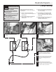
Ignition system 4•7 Fig. 4.8 Location of Digiplex ignition system components (Sec 9) 1 Control unit 2 Distributor 3 Ignition coil 4 TDC sensor 5 Wiring connector plug important that the following precautions are observed. 3 Never start the engine if the battery leads are loose. 4 Do not stop the engine by pulling off a battery lead. 5 Remove the control unit if ambient temperature (paint drying oven) is above 80ºC (176ºF).
4•8 Ignition system Fig. 4.14 Spark plug connections on 903 cc engine (Sec 11) this type is used and the engine is in good condition, the spark plugs should not need attention between scheduled replacement intervals. Spark plug cleaning is rarely necessary and should not be attempted unless specialised equipment is available as damage can easily be caused to the firing ends. 2 At the specified intervals, the plugs should be renewed.
Ignition system 4•9 Fault finding - mechanical breaker ignition system Engine fails to start Engine starts and runs but misfires m m m m m m m m m m m m m m m Loose battery connections Discharged battery Oil in contact points Disconnected ignition leads Faulty condenser Engine overheats, lacks power m Seized distributor weights m Perforated vacuum pipe m Incorrect ignition timing Faulty spark plug Cracked distributor cap Cracked rotor arm Worn advance mechanism Incorrect spark plug gap Incorrect cont
8•1 Chapter 8 Braking system For modifications, and information applicable to later models, see Supplement at end of manual Contents Brake disc - inspection, renovation or renewal . . . . . . . . . . . . . . . . . 6 Brake drum - inspection, renovation or renewal . . . . . . . . . . . . . . . . 8 Brake pedal - removal and refitting . . . . . . . . . . . . . . . . . . . . . . . . . . 18 Caliper - removal, overhaul and refitting . . . . . . . . . . . . . . . . . . . . . .
8•2 Braking system 2 Maintenance 1 2 3 4 Fig. 8.1 Components of the braking system (LHD shown) (Sec 1) Caliper 5 Cap and fluid level sensor 8 Pipeline Hose 6 Vacuum servo unit 9 Hose Master cylinder 7 Rear wheel cylinder 10 Pressure regulating valve Fluid reservoir 1 1 At the weekly service check, inspect the fluid level in the master cylinder reservoir.
Braking system 8•3 3.8B Cylinder body located on caliper bracket 4.7 Rear brake assembly 4.11 Rear hub showing cut-outs on rear face for shoe self-adjuster bosses into its cylinder to accommodate them. This will cause the fluid level to rise in the reservoir.
8•4 Braking system assembly and the flexible pipe, particularly the fixing bracket and union at the car end of the flexible pipe. 3 Have ready a container suitable to catch the brake fluid, and sheets of clean newspaper on which to put parts. 4 Take out the spring clips and locking blocks, and take the caliper off the support bracket. 5 Disconnect the hydraulic flexible pipe at the under wing support bracket and cap both pipe ends.
Braking system 8•5 9 Master cylinder - removal, overhaul and refitting 4 Note: Purchase a repair kit in advance of overhaul. 1 The master cylinder is mounted on the front face of the brake vacuum servo unit (55 and 70 models) or directly to the bulkhead (45 models). 2 Cover the front wings with polythene sheeting or similar material, in case hydraulic fluid spills onto the paintwork of the car during removal of the cylinder.
8•6 Braking system 10.4 Pressure regulating valve bracket and tension spring their originally fitted sequence and note in which direction the seal lips are located. 11 Inspect the surfaces of the piston and cylinder bore. If scoring, corrosion or metal-to-metal rubbing areas are evident, renew the master cylinder complete. 12 If the components are in good condition, discard the oil seals and manipulate the new ones into position, using the fingers only.
Braking system 8•7 11.3 Front hydraulic hose bracket Fig. 8.12 Bleeding a rear wheel cylinder (Sec 12) 12.8 Caliper bleed screw with dust cap fitted The hose ends can then be unclipped from the brackets. The mounting brackets, particularly on the body frame, are not very heavy gauge and care must be taken not to wrench them off (photo). 4 With the flexible hose removed, examine the internal bore. If it is blown through first, it should be possible to see through it.
8•8 Braking system 20 By connecting a pressurised container to the master cylinder fluid reservoir, bleeding is then carried out by simply opening each bleed screw in turn and allowing the fluid to run out, rather like turning on a tap, until no air is visible in the expelled fluid. 21 By using this method, the large reserve of hydraulic fluid provides a safeguard against air being drawn into the master cylinder during bleeding which often occurs if the fluid level in the reservoir is not maintained.
Braking system 8•9 locknut and turn the adjuster nut on the handbrake primary rod (photo). 3 Raise the rear roadwheels and check that they turn freely when the handbrake lever is fully released. 17 Handbrake cable renewal 1 1 There are two cables, either of which may be renewed independently 2 Disconnect the cable, which is to be renewed, from the shoe lever at the brake backplate. 3 Disconnect the longer cable from the primary link or rod and release the cable from its retainers.
9•1 Chapter 9 Electrical system For modifications, and information applicable to later models, see Supplement at end of manual Contents Alternator - maintenance and precautions . . . . . . . . . . . . . . . . . . . . 3 Alternator - overhaul . . . . . . . . . . . . . . . . . . . . . . . . . . . . . . . . . . . . . 5 Alternator - removal and refitting . . . . . . . . . . . . . . . . . . . . . . . . . . . 4 Battery - inspection, charging, removal and refitting . . . . . . . . . . . .
9•2 Electrical system Fuses 1 2 3 4 5 6 7 8 9 10 11 12 13 14 Circuit protected Stop lamps, direction indicator lamps, instrument panel warning lamps, tachometer economy gauge, check control system . . . . . . Windscreen wiper and washer, rear screen wiper/washer, check system panel illumination . . . . . . . . . . . . . . . . . . . . . . . . . . . . . . . . Left front parking, right rear tail lamp, cigar lighter illumination, heater control and clock, digital clock illumination . . . . . . . . . . . . .
Electrical system 9•3 4.2A Alternator mounting 3 Alternator maintenance and precautions 1 To avoid damage to the alternator, the following precautions should be observed. 1 Disconnect the leads from the battery before connecting a mains charger to the battery terminals. 2 Never stop the engine by pulling off one of the battery leads. 3 Disconnect the battery if electric welding is to be carried out on the vehicle.
9•4 Electrical system whilst listening to the starter. Listen to find out if the solenoid clicks into position. If it does not, pull off the solenoid wire, and check it with a test bulb. If the wire is live when the key is turned, but the solenoid does not move, take off the starter and remove it to the bench for overhaul. 8 Starter motor removal and refitting 8.2 Starter motor connections ease the holder out of the alternator.
Electrical system 9•5 9.8 Starter motor dismantled 10.1 Fuse block (later models) 11.4 Unscrewing steering column switch clamp nut 1 Horn relay 2 Heated tailgate window relay 8 Withdraw the solenoid and yoke off the armature and from the drive end bracket. Note the steel and fibre washers and the shims on the armature shaft (photo). 9 Extract the split pin and tap out the engagement lever pivot pin. 10 Pull the rubber packing piece from the drive end bracket.
9•6 Electrical system 13.5A Withdrawing switch panel 13.5B Switch panel fibre optic 14.2A Tailgate contact block them. Carefully release the fibre optic filaments (photos). 6 A push-button switch can be removed by compressing its retaining tabs and pushing it from the panel. 7 A rocker switch can be removed if its knob is pulled off and the switch sections withdrawn from the panel. 8 Reassembly and refitting of both types of switches are reversals of removal and dismantling. 14 Tailgate contacts 14.
Electrical system 9•7 18.1 Headlamp upper fixing screw 18.2 Withdrawing headlamp the tyres correctly inflated and square to a wall, at a distance of 10.0 m (32.8 ft) from it. 4 Mark the wall to correspond with the centres of the headlamps. 5 Switch to dipped beams when the brightest parts of the light pattern should be below the marks on the wall by an amount equal to one tenth of the distance between the floor and the mark on the wall.
9•8 Electrical system 20.1 Interior roof lamp withdrawn 20 Interior lamps bulb renewal 1 Courtesy lamp 1 The lamp lenses, whether roof or pillar mounted, are removed by prising off using a screwdriver inserted under one end (photo). 2 The festoon type bulb is pulled from its spring contacts. Instrument panel lamps 3 Remove the instrument panel hood cover as described in the next Section.
Electrical system 9•9 Fig. 9.5 Windscreen wiper blade fixing (Sec 24) 23.3 Speedometer cable connector at transmission 24.4 Windscreen wiper arm nut 3 Working at the transmission, disconnect the speedometer cable by unscrewing the knurled retaining ring (photo). 4 Withdraw the cable through the bulkhead grommet. 5 Refit the new cable assembly by reversing the removal operations. wiper arm. The blade can then be withdrawn, passing the wiper arm hook through the slot (C) in the blade stretcher (Fig. 9.
9•10 Electrical system 27.4 Tailgate wiper motor 27 Tailgate wiper motor removal and refitting 28.1 Washer fluid reservoir 1 1 Remove the blade and arm as previously described. Unscrew the drive spindle bezel nut. 2 Open the tailgate fully. 3 Unclip and remove the wiper motor cover. 4 Unscrew the mounting screws, withdraw the motor and disconnect the wiring plug (photo). 5 Refitting is a reversal of removal.
Electrical system 9•11 Fig. 9.9 Door speaker mounting (Sec 30) paintwork should the drill slip. Three methods of making the hole are in use: a) Use a hole saw in the electric drill. This is, in effect, a circular hacksaw blade wrapped round a former with a centre pilot drill. b) Use a tank cutter which also has cutting teeth, but is made to shear the metal by tightening with an Allen key. c) The hard way of drilling out the circle is using a small drill, say 1/8 in (3 mm), so that the holes overlap.
9•12 Electrical system 3 The centralised door locking system can operate independently of the key. 4 To gain access to the lock solenoid and linkage, remove the front door trim panel as described in Chapter 12. 5 Disconnect the battery negative lead. 6 Disconnect the electrical wiring plugs from the solenoid within the door cavity. 7 Disconnect the solenoid from the lock lever by removing the clip. 8 Unscrew the two bolts which secure the solenoid to the door and remove it.
Electrical system 9•13 Fig. 9.16 Digital clock controls (Sec 35) A Control button - hour setting B Control button - display (ignition off) C Control button - minute setting D Map reading lamp switch sensors, lamp circuits and the control unit. Corrosion at the terminals may also be a contributory cause. 8 Never short circuit a sensor supply wire or the electronic module will be damaged. the red and green general warning lamps. Unscrew the two monitor fixing bolts.
9•14 Electrical system Fault finding - electrical system No voltage at starter motor Horn fails to operate m m m m m m Blown fuse m Cable or cable connection loose, broken or disconnected m Horn has an internal fault Battery discharged Battery defective internally Battery terminals loose or earth lead not securely attached to body Loose or broken connections in starter motor circuit Starter motor switch or solenoid faulty Voltage at starter motor - faulty motor m m m m Starter brushes badly worn, sti
10•1 Chapter 10 Steering Contents Description and maintenance . . . . . . . . . . . . . . . . . . . . . . . . . . . . . . 1 Fault finding - steering . . . . . . . . . . . . . . . . . . . . . See end of Chapter Steering angles and front wheel alignment . . . . . . . . . . . . . . . . . . . . 8 Steering column - removal, overhaul and refitting . . . . . . . . . . . . . . 5 Steering column lock - removal and refitting . . . . . . . . . . . . . . . . . . 9 Steering gear - overhaul . . . . . . . . . . . . . .
10•2 Steering section of the rack will take the grease into the housing as it returns. 9 Reconnect the tie-rod end to the tie-rod and the eye of the steering arm. Provided the locknut is tightened by only rotating it through the same distance by which it was loosened, the front wheel alignment (tracking) should not have been unduly disturbed. Even so, check the alignment as described in Section 8. 4 Steering wheel removal and refitting 2.
Steering 10•3 Fig. 10.2 Removing steering column shroud screws (Sec 5) Fig. 10.3 Unscrewing combination switch clamp nuts (Sec 5) Fig. 10.4 Renewing steering shaft bushes (Sec 5) 13 Stake the lower end of the tube to retain the bush. 14 Reassembly is a reversal of removal, noting that the universal joint coupling pinch-bolts should pass smoothly through the grooves in the steering shaft. 15 Fit the steering wheel when the roadwheels are in the straight-ahead position.
10•4 Steering Fig. 10.8 Front wheel alignment diagram (Sec 8) Fig. 10.7 Castor angle (Sec 8) A Vertical line B Castor angle (positive) wear. Before considering the steering angles, check that the tyres are correctly inflated, that the front wheels are not buckled, the hub bearings are not worn or incorrectly adjusted and that the steering linkage is in good order, without slackness or wear at the joints.
11•1 Chapter 11 Suspension For modifications, and information applicable to later models, see Supplement at end of manual Contents Fault finding - suspension . . . . . . . . . . . . . . . . . . . See end of Chapter Front coil spring - removal and refitting . . . . . . . . . . . . . . . . . . . . . . 4 Front crossmember - removal and refitting . . . . . . . . . . . . . . . . . . . 7 Front hub carrier - removal and refitting . . . . . . . . . . . . . . . . . . . . . .
11•2 Suspension Fig. 11.1 Front suspension arrangement (Sec 1) 1 General description The front suspension is of independent MacPherson strut type. The rear suspension consists of a beam axle with trailing arms, coil springs and double acting gas-filled telescopic shock absorbers. Operations covering the hubs, roadwheels and tyres are described in Chapter 7. 2 Maintenance 4 1 Periodically check the tightness of all suspension nuts and bolts using a torque wrench.
Suspension 11•3 release its top coil from the strut upper mounting, hold the flats on the strut spindle and unscrew the spindle nut. 8 Take off the upper mounting components and the clamped coil spring. The clamps need not be removed if the spring is to be fitted to a new strut. 9 Commence reassembly by fitting the coil spring onto the strut. Make sure that the smaller coil is at the top and the lower coil is up against its end stop in the spring seat. 10 Check that the strut boot is in position.
11•4 Suspension and remove them. Leave the steering rack hanging loose. 8 Remove the front crossmember mounting bolts and manoeuvre it from the car. 9 Refitting is a reversal of removal. Tighten all nuts and bolts to the specified torque wrench settings and on completion, check the front wheel alignment as described in Chapter 10. 8 Rear shock absorber removal and refitting 6.2 Separating track control arm balljoint from hub carrier 6.
Suspension 11•5 Fig. 11.9 Removing trailing arm pivot bolt (Sec 10) 1 2 3 4 5 6 7 8 Trailing arm bracket Axle beam Buffer Shock absorber top mounting Coil spring Shock absorber Stub axle Hub Fig. 11.8 Rear suspension components (Sec 8) 10 Trailing arm rubber bush renewal 3 1 A worn trailing arm rubber bush may be renewed in the following way. 2 Raise the rear of the car and support securely on axle stands placed under the body side-members or sill jacking points. 3 Remove the roadwheels.
11•6 Suspension Fault finding - suspension Note: Before diagnosing suspension defects, be sure that trouble is not due to incorrect or uneven tyre pressures, in inappropriate combinations.
12•1 Chapter 12 Bodywork For modifications, and information applicable to later models, see Supplement at end of manual Contents Bonnet - removal and refitting . . . . . . . . . . . . . . . . . . . . . . . . . . . . . Bonnet - lock and release . . . . . . . . . . . . . . . . . . . . . . . . . . . . . . . . . Centre console - removal and refitting . . . . . . . . . . . . . . . . . . . . . . . Door - dismantling . . . . . . . . . . . . . . . . . . . . . . . . . . . . . . . . . . . . . . .
12•2 Bodywork 2.4A Door drain hole 2.4B Sill drain with non-return valve can be drained out (photos). Brightwork should be treated in the same way as paintwork. Windscreens and windows can be kept clear of the smeary film which often appears, by the use of proprietary glass cleaner. Never use any form of wax or other body or chromium polish on glass. details on more ambitious repairs involving welding and panel beating.
Bodywork 12•3 affected area with rust-inhibiting paint, if the back of the rusted area is accessible, treat this also. Before filling can take place, it will be necessary to block the hole in some way. This can be achieved by the use of aluminium or plastic mesh, or aluminium tape. Aluminium or plastic mesh, or glass-fibre matting, is probably the best material to use for a large hole.
12•4 Bodywork 7.2 Bonnet hinge of the bonnet or stick strips of masking tape around them as a guide to refitting (photo). 3 With the help of an assistant, support the weight of the bonnet, unbolt the hinges and lift the bonnet from the car. 4 Refitting is a reversal of removal, but do not fully tighten the hinge bolts until the bonnet has been gently closed and its alignment checked.
Bodywork 12•5 9.1B Front bumper upper fixing screw Fig. 12.3 Front bumper (Sec 9) Fig. 12.4 Front bumper upper screws (Sec 9) 10 Front wing removal and refitting 1 1 Remove the headlamp and front parking lamp as described in Chapter 9. 10.4A Unscrewing wing shield screw Fig. 12.5 Front bumper lower screws (Sec 9) 2 Withdraw the side repeater lamp and disconnect the leads. 3 Remove the front roadwheel.
12•6 Bodywork 11.2 Door tidy bin screw 11.3A Removing remote control handle escutcheon 11.3B Remote control handle withdrawn 11.4 Window regulator handle removed 11.6 Removing door trim panel 11.7 Window regulator handle ready for fitting Fig. 12.6 Door glass mounting screw (Sec 12) Fig. 12.7 Removing door weatherseal (Sec 12) Fig. 12.8 Removing door glass (Sec 12) Fig. 12.9 Door window regulator fixing screws (Sec 12) rag between the handle and the door trim panel at its lower gap (photo).
Bodywork 12•7 12.7 Door glass mounting Fig. 12.10 Removing door window regulator (Sec 12) Fig. 12.11 Removing door handle fixing screw (three-door model) (Sec 12) Fig. 12.12 Extracting glass guide channel screw (Sec 12) Fig. 12.13 Removing glass guide channel (Sec 12) Fig. 12.14 Removing door lock fixing screw (Sec 12) 6 Turn the glass very carefully and withdraw it from the door. A new glass is supplied complete with lower mounting.
12•8 Bodywork 13.3 Door lower hinge 13.9 Door lock striker 14.2 Tailgate strut ball cup speakers, central door locking or power operated windows, the electrical leads must be disconnected and withdrawn through the flexible duct before the door hinges are unbolted. Disconnection will require removal of the door trim panel as described in Section 11. 5 It is recommended that the door is unbolted from the hinge, leaving the hinge attached to the body pillar.
Bodywork 12•9 Fig. 12.16 Peeling back lip of windscreen glass weatherseal (Sec 15) Fig. 12.18 Components of opening side window (Sec 18) 17 Fixed side window (five-door) removal and refitting Fig. 12.17 Position of cord for fitting windscreen weatherseal (Sec 15) body so that the bottom edge of the rubber seal engages over the metal flange. 7 With an assistant pressing on the outside of the glass, go inside and pull the cords evenly.
12•10 Bodywork Fig. 12.19 Facia panel fixing screws (Sec 22) 22.5C Facia panel lower mounting screw (left-hand side) 22.5A Facia fixing screw inside glovebox Fig. 12.20 Rear view of facia panel showing fixing screw locations (Sec 22) 1 and 5 Clips 2, 3 and 4 Screws 4 Reach up behind the facia panel on the side opposite to the glove box and unscrew the remaining console fixing screw. 5 Withdraw the console downwards and disconnect the fibre optics from their source.
Bodywork 12•11 24.2 Exterior mirror control knob 24.3 Mirror ring nut and C-spanner 24.4 Withdrawing exterior mirror and trim plate 25.1 Grab handle screw Fig. 12.21 Rear bumper (Sec 26) 24 Rear view mirrors 1 Interior 1 The mirror may be removed after extracting the fixing screws. The mirror is designed to break off if struck. Exterior 2 The mirror is remotely controlled. To remove the mirror, peel back the rubber cover from the control knob (photo).
12•12 Bodywork 28 Sunroof operation and maintenance Fig. 12.24 Prising out sunroof glass panel screw caps (Sec 28) Fig. 12.25 Extracting sunroof panel screw (Sec 28) 1 To unlock the sunroof, bring the control lever down and turn it anti-clockwise. The glass sunroof will partially rise and then slide rearwards. 2 A sliding louvre is provided to decrease noise and airflow. 3 On cars fitted with a sunroof, the interior lamps are of pillar-mounted type.
13•1 Chapter 13 Supplement: Revisions and information on later models Contents Introduction . . . . . . . . . . . . . . . . . . . . . . . . . . . . . . . . . . . . . . . . . . . 1 Specifications . . . . . . . . . . . . . . . . . . . . . . . . . . . . . . . . . . . . . . . . . 2 Routine maintenance - all models from June 1991 . . . . . . . . . . . 3 Engine 903 and 1299/1301 cc . . . . . . . . . . . . . . . . . . . . . . . . . . . . .
13•2 Supplement: Revisions and information on later models Cooling system .................................................................................
Supplement: Revisions and information on later models 13•3 Braking system.................................................................................
13•4 Supplement: Revisions and information on later models 2 Specifications Note: All Specifications are in addition or revisions of those given in the preceding Chapters. Engine General Type . . . . . . . . . . . . . . . . . . . . . . . . . . . . . . . . . . . . . . . . . . . . . . . . . . . . Application: 999 cc (FIRE) . . . . . . . . . . . . . . . . . . . . . . . . . . . . . . . . . . . . . . . . . . . . 1108 cc (FIRE) . . . . . . . . . . . . . . . . . . . . . . . . . . . . . . . . . . . . . . . . . .
Supplement: Revisions and information on later models 13•5 Valve timing clearance: 999 cc . . . . . . . . . . . . . . . . . . . . . . . . . . . . . . . . . . . . . . . . . . . . . . . . . 1108 cc . . . . . . . . . . . . . . . . . . . . . . . . . . . . . . . . . . . . . . . . . . . . . . . . 1372 cc . . . . . . . . . . . . . . . . . . . . . . . . . . . . . . . . . . . . . . . . . . . . . . . . Valve timing: 999 cc: Opens . . . . . . . . . . . . . . . . . . . . . . . . . . . . . . . . . . . . . . . . . . . .
13•6 Supplement: Revisions and information on later models View of front end from below on the 999 cc FIRE engined model 1 2 3 4 5 6 7 8 9 10 View of engine compartment on the 1301 cc Turbo ie engined model 1 2 3 4 5 6 7 8 9 10 11 12 13 14 15 16 17 18 19 20 21 22 23 24 25 Alternator air cooling intake Washer fluid reservoir cap Suspension strut turret Secondary fuel filter Fuel supply hose Coolant expansion tank Brake fluid reservoir cap Ignition system ECU Inlet manifold Excessive pressure switch Air cl
Supplement: Revisions and information on later models 13•7 View of front end from below on the 1031 cc Turbo ie engined model 1 2 3 4 5 6 7 8 9 10 11 12 13 14 15 16 17 18 19 20 Anti-roll bar Exhaust pipe Track control arm Engine centre mounting Gearchange rods Brake caliper Left-hand driveshaft Intermediate driveshaft Right-hand driveshaft Transmission Engine oil drain plug Auxiliary lamp Horn Intercooler Starter motor Oil filter cartridge Oil pressure sender unit Engine oil cooler Right-hand underwing sh
13•8 Supplement: Revisions and information on later models View of front end from below on the 1372 cc ie engine model 1 2 3 4 5 6 7 8 9 10 11 12 13 14 15 16 Oil filter Engine oil drain plug Starter motor Horns Transmission front mounting Front fog lamp and adjuster Driveshaft Transmission rear mounting Gearchange linkage Exhaust downpipe and system joint Anti-roll bar Track control arm Tie-rod balljoint Brake unit Driveshaft damper Underwing shield Lubrication system Oil pump type: 999/1108 cc . . . . .
Supplement: Revisions and information on later models 13•9 Torque wrench settings (continued) Cylinder head bolts: 903 cc (from engine number 581470), 999 and 1108 cc: Stage 1 . . . . . . . . . . . . . . . . . . . . . . . . . . . . . . . . . . . . . . . . . . . . . . Stage 2 . . . . . . . . . . . . . . . . . . . . . . . . . . . . . . . . . . . . . . . . . . . . . . Stage 3 . . . . . . . . . . . . . . . . . . . . . . . . . . . . . . . . . . . . . . . . . . . . . . 1299/1301 cc (10 main bolts): Stage 1 . . .
13•10 Supplement: Revisions and information on later models Cooling system (continued) Radiator fan cut-in temperature: 1301 cc Turbo ie: 1st speed . . . . . . . . . . . . . . . . . . . . . . . . . . . . . . . . . . . . . . . . . . . . 2nd speed . . . . . . . . . . . . . . . . . . . . . . . . . . . . . . . . . . . . . . . . . . . . 1372 cc . . . . . . . . . . . . . . . . . . . . . . . . . . . . . . . . . . . . . . . . . . . . . . . . Radiator fan switch-off temperature: 1301 cc Turbo ie: 1st speed . . . . .
Supplement: Revisions and information on later models 13•11 Weber 32 (continued) Exhaust gas CO at idle . . . . . . . . . . . . . . . . . . . . . . . . . . . . . . . . . . . . . . Fast idle . . . . . . . . . . . . . . . . . . . . . . . . . . . . . . . . . . . . . . . . . . . . . . . . . Float level (with gasket) . . . . . . . . . . . . . . . . . . . . . . . . . . . . . . . . . . . . . Float travel . . . . . . . . . . . . . . . . . . . . . . . . . . . . . . . . . . . . . . . . . . . . . . . Full power jet .
13•12 Supplement: Revisions and information on later models Weber 30/32 DMTE 12/150 Application . . . . . . . . . . . . . . . . . . . . . . . . . . . . . . . . . . . . . . . . . . . . . . . 1299/1301 cc All calibration as for the Weber 30/32 DMTE 10/150 except for the following: Primary Accelerator pump jet . . . . . . . . . . . . . . . . . . . . . . . . . . . . . . . . . . . . . . . 45 Air correction jet . . . . . . . . . . . . . . . . . . . . . . . . . . . . . . . . . . . . . . . . . . . 2.20 Idle jet . .
Supplement: Revisions and information on later models 13•13 Ignition timing (in relation to distributor type) At idle with vacuum hose disconnected and plugged: Marelli SE101A and Ducellier 525473A . . . . . . . . . . . . . . . . . . . . . . . Marelli SE100EX, SE100CX and SE100NX . . . . . . . . . . . . . . . . . . . . . Marelli SE101G . . . . . . . . . . . . . . . . . . . . . . . . . . . . . . . . . . . . . . . . . . Marelli SE100SX . . . . . . . . . . . . . . . . . . . . . . . . . . . . . . . . . . . . .
13•14 Supplement: Revisions and information on later models Ignition timing At idle . . . . . . . . . . . . . . . . . . . . . . . . . . . . . . . . . . . . . . . . . . . . . . . . . . . Maximum advance (at 4000 to 6000 rpm with 0.377 bars/5.5 lbf/in2 vacuum) . . . . . . . . . . . . . . . . . . . . . . . . . . . . Component testing values Ignition coil: Primary resistance at 20ºC (68ºF) . . . . . . . . . . . . . . . . . . . . . . . . . . . . Secondary resistance at 20ºC (68ºF) . . . . . . . . . . . . . . . .
Supplement: Revisions and information on later models 13•15 Torque wrench settings Driveshaft flange connecting bolts (Turbo ie) . . . . . . . . . . . . . . . . . . . . . Final drive output shaft bearing cover bolts (Turbo ie) . . . . . . . . . . . . . . Intermediate shaft support to crankcase (Turbo ie) . . . . . . . . . . . . . . . .
13•16 Supplement: Revisions and information on later models Fuses (903, 999, 1116, 1299/1301 and 1301 cc Turbo ie) (continued) Fuse No. Rating Supplementary fuses at side of main fuse block: A 20 . . . . . . . . . . . . . . . . . . . . . . . . . . . . . . . . . . . . . . . . . . . . . B 30 . . . . . . . . . . . . . . . . . . . . . . . . . . . . . . . . . . . . . . . . . . . . . C 10 . . . . . . . . . . . . . . . . . . . . . . . . . . . . . . . . . . . . . . . . . . . . . D 30 . . . . . . . . . . . . . . . .
Supplement: Revisions and information on later models 13•17 General dimensions, weights and capacities Dimensions Overall length . . . . . . . . . . . . . . . . . . . . . . . . . . . . . . . . . . . . . . . . . . . . . Overall width: Base and Super models . . . . . . . . . . . . . . . . . . . . . . . . . . . . . . . . . . . SX and Turbo models . . . . . . . . . . . . . . . . . . . . . . . . . . . . . . . . . . . . . Height (unladen): 1372 cc (except Turbo) . . . . . . . . . . . . . . . . . . . . . . . . . .
13•18 Supplement: Revisions and information on later models 3 Routine maintenance - all models from June 1991 The maintenance intervals in this manual are provided with the assumption that you, not the dealer, will be carrying out the work. These are the minimum maintenance intervals recommended by us, for vehicles driven daily. If you wish to keep your vehicle in peak condition at all times, you may wish to perform some of these procedures more often.
Supplement: Revisions and information on later models 13•19 Fig. 13.1 Correct method of fitting sump pan sealing strip (Sec 4) 4 Engine 903 and 1299/1301 cc Sump pan sealing strips (903 cc engine) - modification 1 The design of the sealing strips which go between the sump pan and the main bearing caps has been changed. Make sure that the narrower side of the strip fits into the channel in the sump pan.
13•20 Supplement: Revisions and information on later models Fig. 13.3 Longitudinal sectional view of the 999 and 1108 cc engine (Sec 5A) mounted on the front end of the crankshaft and driven by it. 11 The flexible toothed timing belt drives the Fig. 13.4 999 and 1008 cc engine lubrication system (Sec 5A) camshaft and the coolant pump from a sprocket on the front end of the crankshaft. The belt is tensioned by an eccentrically-mounted pulley.
Supplement: Revisions and information on later models 13•21 5B.8A Camshaft sprocket timing mark and cylinder head timing mark in alignment 5B.8B Crankshaft sprocket timing mark and oil pump cover alignment mark (arrowed) 5B.
13•22 Supplement: Revisions and information on later models 5B.22C Camshaft sprocket showing integral key (arrowed) 5B.23C Camshaft lubrication pipe 5B.23A Prising out the camshaft oil feed pipe stub 5B.23D Camshaft bearing cap showing short and long positioning dowels for correct fitting 5B.23B Unscrewing the camshaft bearing/banjo union bolt lubrication pipe (prise the oil feed stub out with a screwdriver), unscrew the remaining bolts and take off the bearing caps (photos).
Supplement: Revisions and information on later models 13•23 5B.32 Disconnecting the throttle cable 5B.34 Inlet manifold coolant hose (A) and brake servo vacuum hose (B) depressurize the fuel system, before disconnecting the fuel pipes and removing the throttle body, as described in Section 9D. 34 Disconnect the coolant and vacuum hoses from the cylinder head and inlet manifold (photo).
13•24 Supplement: Revisions and information on later models 5B.61 Removing the flywheel housing cover plate Sump pan removal and refitting ¡ 60 Drain the engine oil. 61 Unbolt and remove the cover plate from the lower part of the flywheel housing (photo). The two lower bolts retain the gearchange rod support strut. 62 Unscrew the sump pan securing screws and pull the sump pan downwards to remove it (photo). The joint sealant will require cutting with a sharp knife to release the pan.
Supplement: Revisions and information on later models 13•25 5B.77A Removing the oil pump seal 5B.77B Using a socket to fit the new oil pump oil seal 5B.78 Fitting the oil pump 75 If the pump is unworn, refit the rear cover plate and tighten the screws fully. 76 Apply air pressure from a tyre pump to the oil pump oil ducts to clear any sludge or other material and then prime the pump by pouring clean engine oil into its intake duct at the same time turning the oil pump inner gear with the fingers.
13•26 Supplement: Revisions and information on later models 5B.99 Tightening a big-end cap bolt Fig. 13.5 Piston ring arrangement on the 999 cc engine (Sec 5B) 99 Tighten the big-end bolts to the specified torque (photo). The correct torque is important as the bolts have no locking arrangement. After tightening each big-end, check that the crankshaft rotates smoothly. 100 Repeat the operations on the remaining piston/rod assemblies. 101 Refit the oil pump pick-up assembly using a new sealing ring.
Supplement: Revisions and information on later models 13•27 5C.9 Fuel hose identification at pump; inlet hose (1), hose to carburettor (2), return hose (3) 5C.12 Choke cable connection at carburettor 5C.15 Ignition coil HT lead connection 8 Disconnect the heater hose from the inlet manifold. 9 On fuel injection models, depressurize the fuel system (refer to Section 9D). Disconnect the fuel inlet and return hoses from the fuel pump (photo) or throttle body, as applicable.
13•28 Supplement: Revisions and information on later models 5C.23A Exhaust downpipe flange nuts 5C.23B Unscrewing the exhaust pipe lower support bracket bolt 5C.24B Gearchange rod with ball socket connection 5C.24C Gearchange rod support bracket 5C.25A Two of the left-hand driveshaft joint gaiter retaining plate screws (arrowed) 5C.25B Driveshaft joint gaiter withdrawn 5C.26 Left-hand rear (lower) transmission mounting disconnected 5C.31A Right-hand engine mounting disconnected 5C.
Supplement: Revisions and information on later models 13•29 5C.32 Right-hand engine mounting brackets on body and engine 5C.34 Lifting out the engine and transmission 5C.39 Separating the engine and transmission can be lowered to rest on the exhaust and bodymember. 34 Continue to raise the engine and the transmission until it can be removed from the engine compartment and placed on the work surface (photo).
13•30 Supplement: Revisions and information on later models 5C.80 Timing belt tensioner Fig. 13.8 Checking a cam follower for ovality - 999 and 1108 cc engine (Sec 5C) crankcase. If the shells are to be used again, keep them with their respective bearing caps. 70 The thrust washers which control crankshaft endfloat are located in the crankcase, and retained by the turned-over edges of the centre main bearing shell. 71 The engine is now fully stripped.
Supplement: Revisions and information on later models 13•31 5D.6 Fitting a main bearing cap 5D.7A Initial tightening of a main bearing cap bolt 5D.7B Angle-tightening a main bearing cap bolt 6 Fit the main bearing caps in their numbered sequence and the correct way round (photo). 7 Clean the threads of the main bearing cap bolts, lightly oil them and screw them in finger-tight. Tighten all bolts progressively to the specified torque, then check that the crankshaft turns smoothly and evenly (photos).
13•32 Supplement: Revisions and information on later models 5D.16A Crankshaft sprocket showing integral key 5D.16B Tightening the crankshaft sprocket bolt 5D.20 Fitting the timing belt rear cover tighten the sprocket bolt to the specified torque (photos). 17 Refit the clutch to the flywheel as 5D.22 Crankshaft pulley installation described in Chapter 5. Make sure that the driven plate is centralised. 18 Fit the cylinder head. 19 Refit the coolant pump.
Supplement: Revisions and information on later models 13•33 5D.32 Air cleaner hot air collector plate 5D.38 Lifting eye on flywheel housing flange 5D.45 Connecting ball socket type gearchange rod 32 Fit the hot air collector plate for the air cleaner (photo). 33 Refer to Section 10 and fit the distributor. 34 Bolt on the timing belt cover. 35 Fit the camshaft cover, using a new gasket unless the original one is in perfect condition. torque, having located the lifting eye (photo).
13•34 Supplement: Revisions and information on later models 6A.9 Oil pressure sender unit PART B: OPERATIONS POSSlBLE WITH ENGINE IN CAR Camshaft and camshaft carrier - removal and refitting # Warning: Refer to the beginning of Section 9 before starting any work. Fig. 13.
Supplement: Revisions and information on later models 13•35 Fig. 13.13 Cylinder head bolt tightening sequence on the 1301 cc Turbo ie engine (Sec 6B) Fig. 13.14 Piston ring arrangement on the 1301 cc Turbo ie engine (Sec 6B) separately, after the ten main bolts (see Fig. 13.13). 17 The operations described in Chapter 1, Section 28 generally apply, but the following differences should be noted. 18 Remove the engine compartment right-hand shield. This is secured by plastic clips.
13•36 Supplement: Revisions and information on later models 6B.23 Oil cooler Engine oil cooler removal and refitting ¡ 23 The oil cooler is mounted behind the front bumper/spoiler (photo). 24 Disconnect the oil flow and return hoses, either from the cooler or the oil filter cartridge mounting base. Be prepared for some leakage of oil (photos). 25 Unscrew the mounting bolts and remove the oil cooler heat exchanger (photo).
Supplement: Revisions and information on later models 13•37 7A.11 Topping up the engine oil level 1372 cc engine Initial start-up after major overhaul 28 Refer to Chapter 1, Section 45, but note that an oil pressure gauge is fitted to indicate oil pressure. 29 Check the ignition static timing as described in Section 10. 30 Check the engine idle speed and CO level as described in Section 9.
13•38 Supplement: Revisions and information on later models 7B.10 Measuring a valve clearance (No 2 valve shown) 7B.14 Special tool for retaining cam follower in depressed position 7B.15 Removing a shim from a cam follower 9 Turn the engine clockwise using a suitable socket on the crankshaft pulley bolt, until the exhaust valve of No 1 cylinder (valve No 1) is fully closed; ie the cam lobe is pointing directly upwards.
Supplement: Revisions and information on later models 13•39 7B.29 Slide back inspection cover in the timing case 7B.30A Camshaft sprocket timing notch aligned with timing (TDC) pointer in timing case 7B.30B Crankshaft pulley and timing cover timing marks 28 Loosen off the retaining clips and detach the air intake pipe from the air filter. 29 Slide back the inspection cover from the upper end of the timing cover (photo).
13•40 Supplement: Revisions and information on later models 7B.43 Remove the crankshaft Woodruff key if it is loose 7B.45 Withdrawing the auxiliary shaft sprocket 7B.46 Tightening the auxiliary shaft sprocket bolt crankshaft after the pulley securing nut has been removed. Recover the Woodruff key from the end of the crankshaft if it is loose (photo).
Supplement: Revisions and information on later models 13•41 thumb and forefinger at the centre of the run between the auxiliary shaft sprocket and the camshaft sprocket. Using this method it should just be possible to twist the belt through 90º using moderate pressure. 55 To adjust the tension, loosen off the tensioner pulley nut then insert two rods (or screwdrivers) into position in the pulley holes and position a lever between them.
13•42 Supplement: Revisions and information on later models 7B.82 Locating a new camshaft housing gasket on the cylinder head 7B.84 Lowering the camshaft housing on to the cylinder head 7B.85 Tightening a camshaft housing securing bolt 79 Recover the gasket. 80 Removal of the camshaft from the housing, and inspection of the components is described in the following sub-Section. 81 Commence refitting by cleaning the gasket mating surfaces of the camshaft housing and cylinder head.
Supplement: Revisions and information on later models 13•43 7B.119 Locating a new cylinder head gasket on the cylinder block (engine shown on dismantling stand) 98 Commence reassembly by liberally oiling the bearings in the housing, and the oil seal lip. 99 Carefully insert the camshaft into the housing from the blanking plate/distributor end, taking care to avoid damage to the bearings. 100 Refit the blanking plate using a new gasket. 101 Refit the camshaft housing as described previously in this Section.
13•44 Supplement: Revisions and information on later models 7B.122 Tighten the smaller cylinder head bolts to their specified torque setting 7B.130A Inlet (A) and exhaust (B) valves and associate components - 1372 cc engine 7B.130B Valve assembly - 1372 cc engine; insert valve into guide . . . tightened, refit the five smaller (M8 x 1.25) bolts adjacent to the line of the spark plug holes and tighten them to their specified torque wrench setting (photo).
Supplement: Revisions and information on later models 13•45 7B.130I . . . and cap 7B.130J Compress spring and refit the split collets 133 Drain the engine oil from the sump into a suitable container. Disconnect the lead from the engine oil level sensor in the sump. 134 Where applicable, unscrew and remove the bolts retaining the gear linkage mounting bracket and the clutch housing lower cover bolts. Remove the cover from the clutch housing.
13•46 Supplement: Revisions and information on later models 7B.158A Locate the flywheel, washer plate and bolts . . . 7B.158B . . . tighten the bolts to the specified torque 7B.165 Apply sealant to the front oil seal housing/cylinder block joint new oil seal, ensuring that it is correctly orientated, and drive it squarely into position. 149 Refit all disturbed components. necessary, and let it cool naturally without quenching in any way.
Supplement: Revisions and information on later models 13•47 7B.171 Undo the oil pump cover bolts 7B.175 Correct alignment of scribed marks (arrowed) on gears 7B.176 Check gear-to-body clearance 173 Lift the intermediate plate from the oil pump body. 174 The gears can now be removed from the oil pump body. Inspect them for obvious signs of wear or damage, and renew if necessary. 175 Commence reassembly by lubricating the gears with clean engine oil, and refitting them to the casing.
13•48 Supplement: Revisions and information on later models 7B.194A Fitting a ring compressor to a piston 7B.194B Tapping a piston into its bore 7B.195 Assemble the shell bearing to the connecting rod . . . necessary renovated as described later in this Section. 191 Commence refitting as follows. 192 Clean the backs of the bearing shells and the recesses in the connecting rods and big-end caps. 193 Lubricate the cylinder bores with engine oil. 194 Fit a ring compressor to No.
Supplement: Revisions and information on later models 13•49 fitting, as during removal. Note that the compression rings are brittle, and will snap if expanded too far. 206 If new pistons are to be fitted, they must be selected from the grades available, after measuring the cylinder bores. Normally, the appropriate oversize pistons are supplied by the dealer when the block is rebored.
13•50 Supplement: Revisions and information on later models 7C.20 Fuel injector wiring connection 7C.32 Disconnecting the speedometer drive cable from the transmission 7C.36A Engine right-hand mounting 7C.36B Transmission rear mounting 20 Release the retaining clip and detach the wiring connector from the fuel injector connection (photo). 21 Loosen off the front wheel bolts each side, then raise and support the car at the front end on axle stands.
Supplement: Revisions and information on later models 13•51 7C.36C Transmission front mounting fittings are disconnected from the engine and transmission and positioned out of the way.
13•52 Supplement: Revisions and information on later models the new plugs with sealant and tap them squarely into position. 78 Clean and examine the cylinder block as described in paragraphs 2 to 7 of Section 18, Chapter 1. 79 If the auxiliary shaft bushes are excessively worn or are oval, they must be renewed. When the new bushes are installed, they may need to be reamed to suit. The renewal of the auxiliary shaft bushes is therefore best entrusted to an engine reconditioner or FIAT dealer.
Supplement: Revisions and information on later models 13•53 7D.7A Locate the thrust washer . . . 7D.7B . . . sliding them into position each side of the No. 5 main bearing 7D.8 Locate the bearing shells into the main bearing caps . . . bearing caps with a soft non-fluffy rag, then fit the lower halves of the bearing shells to their seats. Again, note that the centre (No. 3) bearing shell is plain, whereas all the other shells have oil grooves (photo).
13•54 Supplement: Revisions and information on later models removal are in place under the engine-to-gearbox bolts. Do not allow the weight of the gearbox to hang on the input shaft as it is engaged with the clutch friction disc. 29 Refit the starter motor, ensuring that the wiring harness bracket is in position on the top bolt. 30 Locate the engine/transmission unit at the front of the car and move it into position under the engine compartment. Attach the lifting sling and hoist as during removal.
Supplement: Revisions and information on later models 13•55 Fig. 13.28 Sectional view of the coolant pump on the 999 and 1108 cc engines (Sec 8A) Coolant pump removal and refitting # 11 The coolant pump is located on the crankshaft pulley end of the engine and is driven by the timing belt. 12 The pump cannot be repaired and must be regarded as disposable. 13 Drain the cooling system. 14 Remove the timing belt cover and then set No. 1 piston to TDC.
13•56 Supplement: Revisions and information on later models 1 2 3 4 5 6 7 8 9 Expansion tank Radiator Electric fan Coolant supply hose (thermostat to radiator) Coolant manifold pipe Coolant pump Coolant supply hose (thermostat to heater matrix) Coolant return hose (heater radiator to manifold pipe) Heater matrix 10 Coolant return hose (inlet manifold to manifold pipe) 11 Coolant return hose (radiator to manifold pipe) 12 Thermostat 13 Fan thermostatic switch Fig. 13.
Supplement: Revisions and information on later models 13•57 8C.14 Bleed screw location on top of the expansion tank (arrowed) 8C.21A Cooling fan and wiring connector 8C.21B Cooling fan switch wiring connector 10 Apply suitable sealant to the threads of the drain plug, then refit and tighten the plug. 11 Dispose of the drained coolant safely, or keep it in a covered container if it is to be re-used. 12 If required, the system can be flushed through as described in Section 2 of Chapter 2.
13•58 Supplement: Revisions and information on later models 8C.40 Coolant pump/alternator bracket bolt removal 35 Clean the mating faces of the thermostat cover and cylinder head, and use a new gasket when refitting the cover. 36 Refill the cooling system as described earlier in this Section. Coolant pump removal and refitting ¡ Note: A new coolant pump gasket must be used on refitting. If the pump is found to be worn it must be renewed as a complete unit as dismantling and repair is not possible.
Supplement: Revisions and information on later models 13•59 Fig. 13.33 Heater pipe shield securing screw positions on later models (Sec 8D) Fig. 13.32 Heater unit facia to main facia retaining screw locations (arrowed) (Sec 8D) the trim cover, undo the retaining screw at the rear of the console. Prise free and release the gear lever gaiter and lift clear the central console. 7 Undo the retaining screws and remove the steering column upper and lower shroud.
13•60 Supplement: Revisions and information on later models 9A.4A Air cleaner toggle clip on the 999 cc model 9 Fuel and exhaust systems Warning: Many of the procedures in this Section require the removal of fuel lines and connections that may result in some fuel spillage. Before carrying out any operation on the fuel system refer to the precautions given in ‘Safety first!’ at the beginning of this Manual and follow them implicitly.
Supplement: Revisions and information on later models 13•61 9A.8A Air cleaner on the 1116 cc, 1299 cc and 1301 cc models 9A.8B Circular type air cleaner element 10 The thermostatically-controlled cold air flap opener is similar to that described in paragraph 7. 11 The air cleaner on the 1372 cc ie engine is of rectangular shape. The element can be removed after releasing the spring clips at the front of the unit, followed by the two screws from its top face.
13•62 Supplement: Revisions and information on later models 9B.2A Weber 32 TLF 4/250 carburettor from anti-run-on solenoid valve side PART B: CARBURETTOR MODELS Carburettor (Weber 32 TLF) description Warning: Refer to the beginning of this Section before starting any work. 1 This carburettor is used on the 999 cc engine and is of the single venturi downdraught type, with a manually-operated choke (cold start).
Supplement: Revisions and information on later models 13•63 9B.18 Removing the Weber 32 TLF carburettor by gripping air cleaner mounting bracket 9B.19 Carburettor insulator block 9B.22 Fuel filter removal from the Weber 32 TLF carburettor 15 Release the clamp screw and pinch-bolt, and disconnect the choke cable. 16 Slacken the throttle cable by releasing the locknut and turning the adjuster sleeve, then slip the cable nipple out of the notch in the throttle spindle quadrant.
13•64 Supplement: Revisions and information on later models 9B.26C Fuel inlet valve body and washer removal from the Weber 32 TLF carburettor 9B.26D Extracting the throttle valve block screws from the Weber 32 TLF carburettor 9B.26E Throttle valve block gasket on the Weber 32 TLF carburettor Fast idle - adjustment (requires removal of the carburettor) 29 Close the choke valve plate by moving the control lever fully. Retain the lever in this position with a rubber band.
Supplement: Revisions and information on later models 13•65 9B.34B Weber 30/32 DMTE carburettor from diaphragm hose side 9B.34C Weber 30/32 DMTE carburettor from choke link side 9B.34D Weber 30/32 DMTE carburettor from throttle link side 9B.34E Weber 30/32 DMTE carburettor from above (with cover removed) 9B.36A Showing idle speed screw (arrowed) and . . . 9B.37A Fuel inlet and return hoses on the Weber 30/32 DMTE carburettor 9B.
13•66 Supplement: Revisions and information on later models 9B.37F Unscrewing a carburettor fixing nut 9B.40 Unscrewing a top cover screw from the Weber 30/32 DMTE carburettor 47 When refitting the new valve, always use a new sealing washer. Float stroke (travel) - see Fig. 3.10 48 The float stroke should be between 42.5 and 43.5 mm when measured from the top cover gasket. Adjust if necessary by bending the tab on the end of the arm. Accelerator pump 9B.
Supplement: Revisions and information on later models 13•67 Fig. 13.39 Sectional view of airflow meter 1301 cc Turbo ie engine (Sec 9C) Fig. 13.
13•68 Supplement: Revisions and information on later models 9C.27B Removing the air cleaner element Idle speed and mixture adjustment ¢ 29 Before carrying out any adjustments, the engine must be at operating temperature, the fan having cut in at second speed and then switched off. 30 Release the locknut and turn the main idle speed screw in the throttle valve housing until the engine idles at the specified speed.
Supplement: Revisions and information on later models 13•69 Fig. 13.43 System control relay connector plug terminals 1301 cc Turbo ie engine (Sec 9C) 9C.55A Disconnecting the duct from the air cleaner 39 Now use the ohmmeter to check the resistance of the following components. microswitch is heard to click immediately the throttle butterfly is opened. Supplementary air valve Fuel injection system mechanical tests 40 Resistance between the terminals should be between 40 and 60 ohms at 20ºC (68ºF).
13•70 Supplement: Revisions and information on later models 9C.60 Fuel pressure regulator Fuel pressure regulator 60 Disconnect the vacuum hose from the regulator (photo). 61 Anticipate some loss of pressurised fuel, and then disconnect the fuel hose from the regulator. Unbolt and remove the unit. Excessive air pressure switch 62 This is screwed into the end of the inlet manifold. Disconnect the electrical leads and unscrew the switch.
Supplement: Revisions and information on later models 13•71 9C.78 Throttle valve housing support bracket 9C.79 Fan thermostatic switch on underside of injector cooling air duct (duct removed for clarity) 9C.80A Extracting a fuel injector screw 9C.80B Fuel injector removal 9C.81A Fuel injectors attached to fuel rail 9C.81B Fuel injector cooling air duct refitting 9C.81C Injector wiring plug refitting 80 The injector retaining plate socket-headed screws may now be removed using an Allen key.
13•72 Supplement: Revisions and information on later models 9C.88A Disconnecting the supplementary air valve hose from the inlet manifold 9C.88B Supplementary air valve (arrowed) 9C.90 Throttle position switch (wiring plug arrowed) Throttle position switch (potentiometer) disconnecting the fuel hoses and wiring plug, and then releasing the mounting clamp. Throttle control linkage general 90 This is located on the left side of the throttle valve housing (photo).
Supplement: Revisions and information on later models 13•73 9C.99C Throttle cable nipple (arrowed) in throttle linkage cut-out PART D: BOSCH MONO-JETRONIC FUEL INJECTION SYSTEM Warning: Refer to the beginning of this Section before starting any work. Description 1 The Bosch Mono-Jetronic fuel injection system fitted to the 1372 cc ie engine and later 999/1108 ‘FIRE’ models is an electronically-controlled single point injection (SPi) system.
13•74 Supplement: Revisions and information on later models 9D.8 Atmospheric air intake for air temperature sensor (1). Also shown are the supply and return fuel line connections (2 and 3) and the throttle position sensor (4) Fig. 13.
Supplement: Revisions and information on later models 13•75 9D.15 Secondary fuel filter element 9D.17A Release the air cleaner end cover retaining clips . . . 9D.17B . . . remove the cover and extract the element 15 Undo the retaining strap bolt and withdraw the filter from its location bracket. Disconnect the inlet and supply hose from the filter. If crimp connectors are fitted they will have to be cut free and new screw type clips fitted (photo).
13•76 Supplement: Revisions and information on later models 9D.26 Fuel pump relay (1), injection control relay (2), Lambda sensor fuse (3) and pump fuse (4) with cover (5) removed 9D.27 Fuel pump relay removal 9D.30 Test lead connected to relay terminals 30 and 87 26 Loosen off the knurled retaining nut and remove the cover from the fuel pump relay. This is located on the left-hand suspension turret in the engine compartment (photo).
Supplement: Revisions and information on later models 13•77 9D.49 Fuel injector unit sensor retaining screw (1). Also shown is the intake air temperature sensor (2) 9D.58A Detach the multiplug (arrowed) . . . 9D.58B . . . for access to the ECU retaining screw (arrowed) air temperature sensor. Undo the retaining screw and remove the sensor from the injector unit (photo). 50 Refit in the reverse order of removal. 64 Detach the brake servo vacuum hose from the connector on the manifold.
13•78 Supplement: Revisions and information on later models c) If the engine develops a misfire, do not drive the car at all (or at least as little as possible) until the fault is cured - the misfire will allow unburned fuel to enter the converter, which will result in its overheating, as noted above. d) DO NOT push- or tow-start the car - this will soak the catalytic converter in unburned fuel, causing it to overheat when the engine does start - see b) above.
Supplement: Revisions and information on later models 13•79 optimum engine operating efficiency. In the event of a system sensor malfunction, errors in data passed to the ECU are overcome by an emergency operation, whereby the ECU supplies the injectors with one of two set injection periods independent of the sensors. One period (2.2 ms) is for idle speed and the other (2.5 ms) is for speeds above idle (actuated when the idle speed contact is opened).
13•80 Supplement: Revisions and information on later models the pump fuse is sound and that its connection (and also that the relay) are clean and secure. 24 The pump can be further checked as described previously for the LE2 fuel injection system fuel pump in Part C of this Section. Supplementary air valve check 25 With the engine at its normal operating temperature, allow it to idle, then pinch the supplementary air valve hose using suitable pliers as shown in Fig. 13.
Supplement: Revisions and information on later models 13•81 Fig. 13.59 Disconnecting the earth leads (arrowed) on the 1372 cc Turbo ie engine (Sec 9E) Fig. 13.57 Detach the vacuum pick-up pipes from the points arrowed on the 1372 cc Turbo ie engine (Sec 9E) Fig. 13.58 removing the inlet manifold mounting bracket from the cylinder head on the 1372 cc Turbo ie engine (Sec 9E) 33 Detach the vacuum pick-up pipes from the points indicated in Fig. 13.57.
13•82 Supplement: Revisions and information on later models are securely and correctly made. 63 Do not reconnect the battery until all the refitting procedures are complete. 64 When the engine is restarted, check around the fuel injection system for any signs of leakage from the fuel supply and return components. Lambda sensor - general Fig. 13.
Supplement: Revisions and information on later models 13•83 9F.16B Unscrewing turbocharger-toexhaust manifold nut 17 Disconnect the air hoses from the turbocharger (photo). 18 Drain the cooling system, and then disconnect the coolant hoses from the turbocharger (photos). 19 Disconnect the oil feed pipe, which has a banjo-type union (photo). 20 Disconnect the oil return pipe which runs to the engine sump pan (photo). 21 Working underneath the car, disconnect the exhaust manifold support bracket (photo).
13•84 Supplement: Revisions and information on later models Fig. 13.66 Turbocharger mounting bracket bolts (arrowed) (Sec 9F) Fig. 13.67 Disconnect the heat exchanger air hose and the oil return pipe (turbocharger-to-sump) (Sec 9F) Fig. 13.68 Turbocharger mounting bracket bolts removal (Sec 9F) Fig. 13.69 Turbocharger coolant pipe-topump bolt location (arrowed) (Sec 9F) 9F.40 Intercooler location (1301 cc engine) 9F.
Supplement: Revisions and information on later models 13•85 Fault finding - turbocharger system Noise or vibration Power loss/indicated boost pressure too low m m m m m m m m m m Worn shaft bearings Lack of lubrication Inlet or exhaust manifold leaking Out-of-balance impeller shaft Engine “pinking” m m m m High boost pressure, caused by faulty wastegate valve Fuel octane rating too low Faulty TDC sensor (ignition advanced) Incorrect spark plugs or plug gaps, or spark plugs worn Turbocharger leaking,
13•86 Supplement: Revisions and information on later models Fig. 13.72 Rotor aligned with arrow on distributor dust shield - 999 and 1108 cc engines (Sec 10) Fig. 13.71 Location of electronic ignition components on early models with breakerless ignition (Sec 10) 1 2 3 4 ECU Ignition coil Distributor Vacuum advance unit 5 Pick-up filter with calibrated opening for atmospheric pressure 6 On 999, 1108 and 1372 cc engines, the distributor is driven from the rear end of the camshaft.
Supplement: Revisions and information on later models 13•87 10.34 Anti-knock sensor Fig. 13.75 Microplex ignition system components on the 1301 cc Turbo ie engine (Sec 10) 10.
13•88 Supplement: Revisions and information on later models Fig. 13.
Supplement: Revisions and information on later models 13•89 10.36 Ignition coil (1) and power module (2) on 1301 cc Turbo ie engine Ignition unit 36 This comprises four elements (photo). a) Power module - receives the ignition advance command and controls the conduction angle of the primary current and energy stored in the coil. b) Dissipater plate - eliminates the heat which is generated by the high volume of current. c) Ignition coil with low primary resistance.
13•90 Supplement: Revisions and information on later models Power module (1372 cc) 54 Proceed as described in paragraph 53. Anti-knock sensor 55 If “pinking” occurs, or loss of power is noticed, test the sensor by substitution of a new one. Ignition coil 56 Disconnect the leads from terminals 1 and 15 on the coil before testing. 57 Using the ohmmeter, check the resistance of the primary winding. This should be between 0.31 and 0.37 ohms (1301 cc) or 0.40 to 0.
Supplement: Revisions and information on later models 13•91 1 Connection point (lines connected to the intake manifold) 2 ECU 3 Ignition coil 4 Distributor 5 Engine flywheel (with five pins) 6 On/off switch (if fitted) for advance reduction 7 On/off switch 2 (if fitted) for curves 8 Battery 9 Spark plugs 10 Tachometer 11 Diagnostic socket 12 Engine speed and TDC sensor 13 To check actuator idle speed 14 To terminal no. 1 of injection control unit (rpm signal) Fig. 13.
13•92 Supplement: Revisions and information on later models 10.70 Ignition distributor and HT lead connections on the 1372 cc ie engine Distributor (Digiplex Z) removal and refitting # 70 Proceed as described in paragraphs 14 to 21. When refitting the distributor, ensure that the engine is still set at the TDC position. Engage the rotor arm into position on the shaft so that its lug engages in the slot in the top end of the drive spindle.
Supplement: Revisions and information on later models 13•93 mounted in-line with and just forward of the clutch pedal. The operating cylinder is mounted within a housing on top of the transmission. The fluid reservoir is located in the engine compartment and is mounted on the left-hand side near the bulkhead. No settings or specific procedures are given by the manufacturer at the time of writing. Maintenance (hydraulic clutch) ¡ 7 Periodically check the fluid level in the reservoir.
13•94 Supplement: Revisions and information on later models at the gear lever end as described in Chapter 6, Section 3. 5 Disconnect the rods at the transmission end by unscrewing the nuts and bolts which connect the linkage rods to the selector rods (photo). 6 Extract the spring clip which retains the end of the short link rod (photo). Gearchange linkage (Antiskid models) - general 11.25 Clutch operating cylinder showing hydraulic line connection and bleed nipple (arrowed) 11.
Supplement: Revisions and information on later models 13•95 final drive unit. The inboard end of each driveshaft locates in the differential. All helical gear clusters are in constant mesh, with the fifth gear assembly located on an intermediate plate mounted on the rear end of the gearbox. Gear engagement is made by sliding synchromesh hubs. Gearchanges are made via a central floor-mounted gear lever.
13•96 Supplement: Revisions and information on later models Fig. 13.91 Exploded view of the gear selector lever, rod and linkage components on 1372 cc models (Sec 12) require maintenance other than general inspection for wear in the linkage joints. If excessive wear is found in any of the joints, they can be individually detached and renewed. 13 Access to the control rods is eased by detaching and lowering the exhaust system from the exhaust manifold.
Supplement: Revisions and information on later models 13•97 12B.24A Starter motor electrical connection . . . 12B.24B . . . and retaining bolts (arrowed) on the 1372 cc ie engine 27 The engine must now be supported at its left-hand end. If the engine/transmission lift bracket is unbolted it can be attached at another suitable position on the engine and the lift sling/tool attached to it, but take care not to attach it to a weak fixing point.
13•98 Supplement: Revisions and information on later models 1 Sliding part of gear lever 2 Reverse gear inhibitor device flexible control cable 3 Gear selector control rod 4 Gear engagement control cable 5 Gear selector adjustable control rod 6 Gear selector and engagement control shaft 7 Reverse gear inhibitor device Fig. 13.94 C514 type 5-speed transmission PART C: 999 CC AND 1108 CC WITH C514 TYPE TRANSMISSIONS Description 1 A new 5-speed transmission was introduced to selected models during 1992.
Supplement: Revisions and information on later models 13•99 Fig. 13.98 Components of the intermediate driveshaft - Turbo ie models (Sec 13) Fig. 13.97 Crimping the driveshaft boot securing band (Sec 13) 3 The boot retaining band must be crimped using suitable pinchers at the highest point on the boot.
13•100 Supplement: Revisions and information on later models 13.21 Outer track reference groove Fig. 13.101 Correct position of driveshaft damper weight on 1108 cc and 1372 cc ie models (Sec 13) Dimensions in mm 13.24 Right-hand driveshaft damper weight 20 When reassembling, pack the joint with special FIAT Tutela MRM2 lubricant; if this is not available, use molybdenum disulphide grease.
Supplement: Revisions and information on later models 13•101 14B.4 Unscrewing the caliper cylinder housing lower guide bolt 14B.6 Disc pad and anti-rattle spring removal 14B.10 Applying thread-locking fluid to the bolt threads 4 Using a ring spanner and an open-ended spanner, unscrew and remove the caliper cylinder housing lower guide bolt (photo). Release the upper bolt, but do not remove it. 5 Swivel the cylinder housing upwards and tie it up out of the way.
13•102 Supplement: Revisions and information on later models 14B.29 Rear disc pad 14B.36 Disconnecting the handbrake cable from the caliper lever 14B.42 Unscrewing a rear caliper bracket bolt 29 Fit the new pads, complete with anti-rattle springs (photo). 30 Refit the caliper using new self-locking bolts, or if not available, apply thread-locking fluid to clean threads of the original bolts. Tighten the bolts to the specified torque.
Supplement: Revisions and information on later models 13•103 1 Electronic control unit (ECU) 2 Roadwheel speed sensors 3 Pressure modulators 4 Vacuum reservoir 5 Check valve 6 Air cleaner 7 Load proportioning (pressure regulating) valves 8 Vacuum switch 9 ECU relay 10 System fault warning lamp relay 11 System fault warning lamp 12 Brake stop lamp switch Fig. 13.
13•104 Supplement: Revisions and information on later models 15.8 Remove the wheel arch lower guard panel for access to the alternator 12 Disconnect the air cooling hose from the rear cover of the alternator, and then unscrew the fixing nuts and take off the rear cover with hose spout. Mark the position of the cover on the alternator before removing it, so that the spout will be correctly positioned when refitted (photos).
Supplement: Revisions and information on later models 13•105 15.23B Starter motor and wiring connections on the 1372 cc ie engine Starter motor brushes (later models) - renewal # 25 When renewing the starter motor brushes on later models, the old brushes will need to be crushed (in a vice or with a hammer) and their leads then soldered to the new brushes. Fuses - later models 26 The fuse arrangement is slightly different on later models, but the circuits protected are still identified by a symbol.
13•106 Supplement: Revisions and information on later models 15.34 Headlamp dim-dip transformer 15.37A Undo the retaining bolts . . . 15.37B . . . and withdraw the front fog lamp unit . . . adjustment procedures are the same as those outlined for the previous model units in Chapter 9, but ensure that the load compensation lever is turned to the “O” (normal load setting) position before making any adjustments. on parking lamps only in built-up areas.
Supplement: Revisions and information on later models 13•107 15.45C . . . and the lower column shroud . . . 15.47A Undo the retaining screw . . . 47 Loosen off the switch-to-column clamp screw, disconnect the wiring connectors to the switch and withdraw the switch from the column (photos). 48 Refit in the reverse order of removal, but ensure that the lug of the switch aligns with the slot in the column as it is fitted into position. Check for satisfactory operation of the switches on completion.
13•108 Supplement: Revisions and information on later models 15.59A . . . withdraw the instrument panel . . . Auxiliary control panel (later models) removal and refitting ¡ 61 Disconnect the battery negative lead. 62 Insert the flat of a screwdriver under the trim piece at the end of the auxiliary panel as shown and prise it free. Repeat the procedure and remove the trim piece at the other end of the panel (photo). 63 Undo the retaining screws, withdraw the panel from the facia.
Supplement: Revisions and information on later models 13•109 15.80A Prising free the roof-mounted spotlamp 83 Refitting is a reversal of the removal procedure. Reset the clock on completion. Central door locking system 15.80B Roof-mounted spotlamp bulb removal Cigar lighter (later models) removal and refitting ¡ 84 Certain later models, equipped with a central door locking system, have an infra-red remote control for opening the door locks.
13•110 Supplement: Revisions and information on later models 15.98A Remove the wiper motor retaining screws . . . 15.98B . . . separate the wiper motor from its cover . . . As it is lifted, invert it and detach the washer hose from the washer nozzle (photos). 97 Where applicable, detach and remove the washer reservoir from the recess in the front of the windscreen to allow access to the wiper motor. 98 Unscrew and remove the two wiper motor retaining screws.
Supplement: Revisions and information on later models 13•111 16.3 Anti-roll bar clamp Door closure sensor 117 The sensor consists of a microswitch within the lock. The switch actuates the warning lamp according to whether the lock is in the open or closed mode. Check control system sensors testing Brake fluid level sensor 118 With the fluid level correct, switch on the ignition and depress the centre of the reservoir cap.
13•112 Supplement: Revisions and information on later models 17.4 Interior mirror base 17.5 Interior mirror mounting plate 17.7A Exterior mirror trim plate push it towards the windscreen; the ball socket will release (photo). 5 Extract the screws from the mounting plate (photo). 6 When refitting the mirror, engage the front of the socket on the ball and then twist the mirror rearwards and upwards. models. This is simply secured by two self-tapping screws (photo).
Supplement: Revisions and information on later models 13•113 17.19A Extracting a radiator grille screw 17.19B Prising down a radiator grille clip 18 Refitting of all components is a reversal of removal. bolts and captive nuts but to reach them, the underwing shields must be released and pulled away. 26 Disconnect the leads from the auxiliary lamps which are mounted in the spoiler, and then lift the bumper/spoiler from the car.
13•114 Supplement: Revisions and information on later models 17.34A Armrest electric window switches the ring nut which secures the handle to the glass. 33 When refitting the screws or ring nut to the glass, make sure that the insulating washers are in good condition to prevent metal-to-glass contact. 17.
Wiring diagrams 14•1 Component key for wiring diagrams 1 to 29 Note: Not all the items listed will be fitted to all models No 00200 00500 01001 01202 01203 01206 01207 01252 01253 01254 01255 01400 01401 01420 01500 01502 01504 02001 02010 02011 02012 02013 02015 02210 02215 02400 02405 02490 02492 03000 03002 03003 03004 03005 03006 03007 03008 03028 03029 03034 03035 03036 03053 03059 03060 03110 03114 03123 03142 03144 03145 03305 03306 Description Alternator with built-in regulator Battery Starter mot
14•2 Wiring diagrams Component key for wiring diagrams 1 to 29 (continued) Note: Not all the items listed will be fitted to all models No 06355 06365 06368 06385 06800 06801 06802 07000 07001 07003 07015 07016 07020 07021 07022 07023 07037 07050 07051 07052 07060 07107 07109 07191 07192 07400 07410 07415 07420 07430 07460 07461 Description Battery charging warning light Choke warning light Antiskid system failure lamp Heated rear screen warning light Horn Right horn Left horn Coolant level sensor Engine o
Wiring diagram 2 - starting, charging, oil pressure and low brake fluid (Comfort and ES models) Wiring diagrams 14•3 Wiring diagram 1 - starting, ignition, charging, oil pressure, low brake fluid, choke warning light and handbrake “on” (S and SX models) 14
14•4 Wiring diagrams Wiring diagram 3 - direction indicators, hazard warning lamps, brake stoplamps and horn (S and SX models) Wiring diagram 4 - direction indicators, hazard warning lamps, brake stoplamps and horn (Comfort and ES)
Wiring diagram 6 - electronic ignition, fuel cut-off device and economy gauge (ES models) Wiring diagrams 14•5 Wiring diagram 5 - front parking lamps, rear number plate lamp and fuel gauge (Comfort, ES, S and SX models) 14
14•6 Wiring diagrams Wiring diagram 7 - headlamps, reversing lamps and front and rear foglamps (SX model) Wiring diagram 8 - headlamps, reversing lamps and rear foglamps (Comfort, ES and S models)
Wiring diagram 10 - windscreen wash/wipe, radiator fan and coolant temperature sensor (Comfort and ES models) Wiring diagrams 14•7 Wiring diagram 9 - windscreen wash/wipe, radiator fan, coolant temperature sensor, heated rear screen and instrument panel illumination 14
14•8 Wiring diagrams Wiring diagram 11 - courtesy lamps, heater fan, heater illumination, cigar lighter, digital clock and radio (S and SX models) Wiring diagram 12 - courtesy lamps, heater fan and heater illumination (Comfort and ES models)
Wiring diagram 14 - tachometer, digital clock, map reading lamp and vacuum gauge (Comfort, ES, S and SX models) Wiring diagrams 14•9 Wiring diagram 13 - heated rear screen and rear wash/wipe (S and SX models) 14
14•10 Wiring diagrams Wiring diagram 15 - central door locking and electric windows (S and SX models) Wiring diagram 16 - headlamp dim-dip system (1987-on models)
Wiring diagrams 14•11 14 Wiring diagram 17 - check panel (S and SX models)
14•12 Wiring diagrams Wiring diagram 18 - check panel with trip master (SL model)
Wiring diagrams 14•13 Wiring diagram 19 - ignition and idle cut-out (later 45 models) 14 Wiring diagram 20 - ignition cut-off device, tachometer and accelerator pump cut-out (60 and 70 models)
14•14 Wiring diagrams Wiring diagram 21 - starting, charging, Microplex ignition, LE-2 Jetronic fuel injection, fuel pump and fuel injector cooling fan (1301 cc Turbo ie model)
Wiring diagram 23 - courtesy lamps, heater fan, heater illumination, cigar lighter, digital clock, radio, low oil pressure lamp, oil pressure switch, oil temperature gauge and tachometer (1301 cc Turbo ie model) Wiring diagrams 14•15 Wiring diagram 22 - direction indicators, hazard warning lamps, brake stoplamps, horn and low brake fluid sensor (1301 cc Turbo ie model) 14
14•16 Wiring diagrams Wiring diagram 24 - dipped headamps, headlamp main beam, foglamps (front and rear) and reversing lamps (1301 cc Turbo ie model) Wiring diagram 25 - front parking lamps, rear number plate lamp, fuel gauge and low level warning lamp, and instrument panel illumination (1301 cc Turbo ie model)
Wiring diagram 27 - electric windows (1301 cc Turbo ie model) Wiring diagrams 14•17 Wiring diagram 26 - windscreen wash/wipe, radiator fan, heated rear screen, instrument panel fibre optic, coolant temperature gauge and rear screen wash/wipe (1301 cc Turbo ie model) 14
14•18 Wiring diagrams Wiring diagram 28 - check panel (1301 cc Turbo ie model)
Wiring diagrams 14•19 14 Wiring diagram 29 - Antiskid braking system (1301 cc Turbo ie model - where fitted)
14•20 Wiring diagrams Component key for wiring diagrams 30 to 52 Note: Not all the items listed will be fitted to all models No 1 2 3 4 5 6 6A 7 8 9 10 11 12 13 14 15 16 17 18 19 20 21 22 23 24 25 26 27 28 29 30 31 32 33 34 35 36 37 38 39 40 41 42 43 44 45 46 Description Injector cooling fan Left front light cluster Left foglamp Left front engine compartment earth Radiator cooling fan Double contact thermostatic switch on engine radiator Thermostatic switch on engine radiator Left horn Right horn Resistor
Wiring diagrams 14•21 Component key for wiring diagrams 30 to 52 (continued) Note: Not all the items listed will be fitted to all models No Description 111 Push button on left front pillar for centre courtesy light 112 Front electric windows switch panel, driver’s side 113 Join between dashboard cable and adjustable map reading light cables 114 Join with left front electric window cables 115 Join between dashboard cable and rear cables 116 Join between rear cable and courtesy light cables 117 Left front sp
14•22 Wiring diagrams * To the rev counter (only for the 999 SX – 1108 SX) ** Non-existent for the 903 Wiring diagram 30 - starting, charging, ignition, low oil pressure and choke warning lamps (1990-on 45, and 55 models)
Wiring diagrams 14•23 * To the rev counter Wiring diagram 31 - starting, charging, Digiplex 2 ignition, SPi fuel injection, fuel pump and low oil pressure (1990-on 70 SX and 1.
14•24 Wiring diagrams * To the rev counter ** Only for the 1372 Turbo with A.B.S.
Wiring diagrams 14•25 * Only for 1372 S ie – 1372 SX ie Wiring diagram 33 - parking lamps, main/dipped headlamps, headlamp flasher and rear number plate lamp (1990-on 45, 55, 70 and 1.
14•26 Wiring diagrams * Only for 1116 S (CTX) and 1372 (CTX) versions ** Only for 1116 S (CTX) and 1372 Turbo ie versions Wiring diagram 34 - parking lamps, main/dipped headlamps, headlamp flasher and rear number plate lamp (1372 cc Turbo ie models)
Wiring diagrams 14•27 14 Wiring diagram 35 - direction indicators, hazard warning lamps, reversing lamps and brake stop-lamps (1990-on 45, 55, 70 and 1.
14•28 Wiring diagrams Wiring diagram 36 - direction indicators, hazard warning lamps, reversing lamps and brake stop-lamps (1372 cc Turbo ie model)
Wiring diagrams 14•29 14 Wiring diagram 37 - rear foglamps (1990-on 45 and 55 models)
14•30 Wiring diagrams Wiring diagram 38 - front and rear foglamps (1990-on 70 SX and 1.
Wiring diagrams 14•31 14 Wiring diagram 39 - front and rear foglamps (1372 cc Turbo ie model)
14•32 Wiring diagrams Wiring diagram 40 - courtesy lamps and instrument panel lamps (1990-on 45, 55, 70 and 1.
Wiring diagrams 14•33 14 Wiring diagram 41 - courtesy lamps and instrument panel lamps (1372 cc Turbo ie model)
14•34 Wiring diagrams Wiring diagram 42 - horns, heated rear screen and windscreen/rear screen wash/wipe (1990-on 45 and 55 models)
Wiring diagrams 14•35 14 Wiring diagram 43 - horns, heated rear screen and windscreen/rear screen wash/wipe (1990-on 70 SX and 1.
14•36 Wiring diagrams Wiring diagram 44 - horns, heated rear screen, windscreen/rear screen wash/wipe and headlamp wash/wipe (1372 cc Turbo ie model)
Wiring diagrams 14•37 14 Wiring diagram 45 - radiator cooling fan, heater, radio and cigar lighter (1990-on 45, 55, 70 and 1.
14•38 Wiring diagrams Wiring diagram 46 - radiator cooling fan, heater, radio and cigar lighter (1372 cc Turbo ie model)
Wiring diagrams 14•39 *Only for 1372 S ie – 1372 SX ie – 1697 D ** Only for D versions s Only for SX versions 14 Wiring diagram 47 - fuel gauge, tachometer, digital clock, brake fluid and handbrake warning lamp (1990-on 45, 55, 70 and 1.
14•40 Wiring diagrams Wiring diagram 48 - fuel gauge, tachometer, digital clock, brake fluid level sensor, handbrake-on switch, brake pad wear sensor, door ajar switch and oil pressure/temperature sender units (1372 cc Turbo ie model)
Wiring diagrams 14•41 14 Wiring diagram 49 - electric windows and central locking (1990-on 3-door models)
14•42 Wiring diagrams Wiring diagram 50 - electric windows and central locking (1990-on 5-door models)
Wiring diagrams 14•43 14 Wiring diagram 51 - Antiskid braking system (1372 cc Turbo ie model - where fitted)
14•44 Wiring diagrams Wiring diagram 52 - check panel (1990-on 5-door models (3-door similar)
MOT Test Checks REF•1 This is a guide to getting your vehicle through the MOT test. Obviously it will not be possible to examine the vehicle to the same standard as the professional MOT tester. However, working through the following checks will enable you to identify any problem areas before submitting the vehicle for the test. Where a testable component is in borderline condition, the tester has discretion in deciding whether to pass or fail it.
REF•2 MOT Test Checks Electrical equipment M Switch on the ignition and check the operation of the horn. M Check the windscreen washers and wipers, examining the wiper blades; renew damaged or perished blades. Also check the operation of the stop-lights. M Inspect both front brake flexible hoses for cracks or deterioration of the rubber. Turn the steering from lock to lock, and ensure that the hoses do not contact the wheel, tyre, or any part of the steering or suspension mechanism.
MOT Test Checks Exhaust system M Start the engine. With your assistant holding a rag over the tailpipe, check the entire system for leaks. Repair or renew leaking sections. Front and rear suspension and wheel bearings M Starting at the front right-hand side, grasp the roadwheel at the 3 o’clock and 9 o’clock positions and shake it vigorously. Check for free play or insecurity at the wheel bearings, suspension balljoints, or suspension mountings, pivots and attachments.
REF•4 MOT Test Checks M Examine the handbrake mechanism, checking for frayed or broken cables, excessive corrosion, or wear or insecurity of the linkage. Check that the mechanism works on each relevant wheel, and releases fully, without binding. M It is not possible to test brake efficiency without special equipment, but a road test can be carried out later to check that the vehicle pulls up in a straight line.
Tools and Working Facilities Introduction A selection of good tools is a fundamental requirement for anyone contemplating the maintenance and repair of a motor vehicle. For the owner who does not possess any, their purchase will prove a considerable expense, offsetting some of the savings made by doing-it-yourself. However, provided that the tools purchased meet the relevant national safety standards and are of good quality, they will last for many years and prove an extremely worthwhile investment.
REF•6 Tools and Working Facilities Sockets and reversible ratchet drive Valve spring compressor Piston ring compressor Piston ring removal/installation tool Cylinder bore hone Three-legged hub and bearing puller Micrometer set Vernier calipers Dial test indicator and magnetic stand Compression testing gauge Clutch plate alignment set Brake shoe steady spring cup removal tool
Tools and Working Facilities M Impact screwdriver M Micrometer and/or vernier calipers (see illustrations) M Dial gauge (see illustration) M Universal electrical multi-meter M Cylinder compression gauge (see illustration) M Clutch plate alignment set (see illustration) M Brake shoe steady spring cup removal tool (see illustration) M Bush and bearing removal/installation set (see illustration) M Stud extractors (see illustration) M Tap and die set (see illustration) M Lifting tackle M Trolley jack Buying to
REF•8 General Repair Procedures Whenever servicing, repair or overhaul work is carried out on the car or its components, observe the following procedures and instructions. This will assist in carrying out the operation efficiently and to a professional standard of workmanship. Joint mating faces and gaskets When separating components at their mating faces, never insert screwdrivers or similar implements into the joint between the faces in order to prise them apart.
Fault Finding Introduction The vehicle owner who does his or her own maintenance according to the recommended schedules should not have to use this section of the manual very often. Modern component reliability is such that, provided those items subject to wear or deterioration are inspected or renewed at the specified intervals, sudden failure is comparatively rare. Faults do not usually just happen as a result of sudden failure, but develop over a period of time.
REF•10 Fault Finding Spares and tool kit Most vehicles are supplied only with sufficient tools for wheel changing; the Maintenance and minor repair tool kit detailed in Tools and working facilities, with the addition of a hammer, is probably sufficient for those repairs that most motorists would consider attempting at the roadside. In addition a few items which can be fitted without too much trouble in the event of a breakdown should be carried.
Fault Finding Engine cuts out and will not restart Engine cuts out suddenly – ignition fault m Loose or disconnected LT wires m Wet HT leads or distributor cap (after traversing water splash) m Coil failure (check for spark) m Other ignition fault (see Chapter 4) Engine misfires before cutting out – fuel fault m Fuel tank empty m Fuel pump defective or filter blocked (check for delivery) m Fuel tank filler vent blocked (suction will be evident on releasing cap) m Carburettor needle valve sticking m Carbure
REF•12 Buying spare parts & Vehicle identification numbers Buying spare parts Spare parts are available from many sources, for example, FIAT garages, other garages and accessory shops, and motor factors. Our advice regarding spare parts is as follows: Officially appointed FIAT garages - This is the best source of parts which are peculiar to your car and otherwise not generally available (eg complete cylinder heads, internal gearbox components, badges, interior trim etc).
Glossary of Technical Terms A ABS (Anti-lock brake system) A system, usually electronically controlled, that senses incipient wheel lockup during braking and relieves hydraulic pressure at wheels that are about to skid. Air bag An inflatable bag hidden in the steering wheel (driver’s side) or the dash or glovebox (passenger side). In a head-on collision, the bags inflate, preventing the driver and front passenger from being thrown forward into the steering wheel or windscreen.
REF•14 Glossary of Technical Terms Catalytic converter A silencer-like device in the exhaust system which converts certain pollutants in the exhaust gases into less harmful substances. Catalytic converter Circlip A ring-shaped clip used to prevent endwise movement of cylindrical parts and shafts. An internal circlip is installed in a groove in a housing; an external circlip fits into a groove on the outside of a cylindrical piece such as a shaft. Clearance The amount of space between two parts.
Glossary of Technical Terms G I Gap The distance the spark must travel in jumping from the centre electrode to the side electrode in a spark plug. Also refers to the spacing between the points in a contact breaker assembly in a conventional pointstype ignition, or to the distance between the reluctor or rotor and the pickup coil in an electronic ignition.
REF•16 Glossary of Technical Terms Rotor In a distributor, the rotating device inside the cap that connects the centre electrode and the outer terminals as it turns, distributing the high voltage from the coil secondary winding to the proper spark plug. Also, that part of an alternator which rotates inside the stator. Also, the rotating assembly of a turbocharger, including the compressor wheel, shaft and turbine wheel. Runout The amount of wobble (in-and-out movement) of a gear or wheel as it’s rotated.
Index REF•17 Note: References throughout this index relate to Chapter•page number A Accelerator cable - 3•12, 13•80 Accelerator control system - 13•75 Accelerator pump - 3•7, 3•8, 3•11, 13•66 Acknowledgements - 0•4 Aerial - 9•10 Air bags - 0•5 Air cleaner - 3•4, 13•60, 13•69, 13•67, 13•75, 13•79 Air pressure switch - 13•70 Air temperature sensor - 13•76 Airflow meter - 13•67, 13•69, 13•80 Alternator - 9•3, 13•58, 13•103, 13•104 Alternator fault - 9•14 Anti-flooding device - 3•8, 3•9, 3•10, 3•11, 13•64 An
REF•18 Index F H Facia - 12•10, 13•107 Fan - 2•3, 13•57, 13•71, 13•84 Fast idle adjustment - 3•7, 3•9, 3•10, 3•11, 13•64 Fault finding - REF`•9 et seq Fault finding - braking system - 8•9 Fault finding - clutch - 5•3 Fault finding - cooling and heating systems - 2•8 Fault finding - driveshafts and hubs - 7•6 Fault finding - Econometer - 9•12 Fault finding - electrical system - 9•14, REF•9 Fault finding - engine - 1•35, 1•36, 2•8, 3•13, 4•9, 13•92, REF•10, REF•11 Fault finding - fuel system - 3•9, 3•13,
Index REF•19 S T V Safety first - 0•5 Safety pressure switch - 13•90 Scalding - 0•5 Scratches in bodywork - 12•2 Screw threads and fastenings - REF•8 Seat belts - 12•10, REF•2 Seats - 12•9, REF•2 Servo unit - 8•8, 13•103 Shock absorbers - 11•4, REF•2, REF•3 Shoes - 8•3 Side light - 9•7 Side repeater lamp - 9•7 Spares - REF•10, REF•12 Spark plugs - 4•7, 13•92 Speedometer - 9•8 Spotlamp - 13•108 Springs - 11•3, 11•4, REF•3 Starter motor - 9•4, 13•104, 13•105 Starter fault - 1•35, 9•14, 13•92, REF•10 Stee
REF•20 Preserving Our Motoring Heritage < The Model J Duesenberg Derham Tourster. Only eight of these magnificent cars were ever built – this is the only example to be found outside the United States of America Almost every car you’ve ever loved, loathed or desired is gathered under one roof at the Haynes Motor Museum.