
User's Manual


9
INSTALLATION
B
BYPASS
DIMMER
L
N
B
BYPASS
DIMMER
L
N
DIMMER DIMMER
L
N
B
B
L
N
single switch double switch
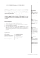
Wiring diagram no. 2 - 3-wire connection
2-wire connection
Wiring diagram no. 3 - connecting FGB-002
3-wire connection
DIMMER DIMMER
L
N
B
B
L
N
single switch double switch
Wiring diagram no. 1 - 2-wire connection
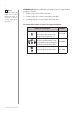
NOTE
Switch connected to
the S1 terminal is a
master switch. It acti-
vates the basic func-
tionality of the Dim-
mer 2 (turning the
light on/o, dimming)
and starts the learning
mode (Add/Remove).
The switch connected
to the S2 terminal is an
optional switch and
pushing it without
changing the congu-
ration parameters will
not aect the status of
the device. Function-
ality of the switches
can be reversed by
adjusting advanced
parameter (see „Ad-
vanced parameters”
on page 22).
i