
User's Manual


7
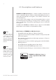
TEMPERATURE SENSOR
#4: Temperature sensor
CAUTION
Connected the device
in accordance with
the wiring diagram.
Incorrect wiring may
be dangerous or result
in the device break-
down.
!
NOTE
Connecting/discon-
necting the temper-
ature sensor to/from
previously added
Door/Window Sensor,
requires removing
and re-adding the
device to the Z-Wave
network.
i
The DS18B20 temperature sensor may be installed anywhere where
temperature readouts are necessary. If adequately protected, the
DS18B20 sensor may be installed in humid conditions, under water,
sealed in concrete or placed under the oor.
CAUTION
Connecting devic-
es and sensors other
than DS18B20 is not
allowed.
!
To activate the device with temperature measurement functionality:
1. Open the cover.
2. Connect the temperature sensor to terminals of the device
according to the diagram:
3. Add the device (see “Adding/removing the device” on page 6).
4. Install the device (see “Physical installation” on page 9).
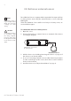
GND
max 30m
TD (DQ)
TP (VDQ)
321
(BOTTOM VIEW)
(TOP VIEW)
TMP
DS18B20
123
321
GND
TD (DQ)
TP (VDQ)
DS18B20
+
-
TP
(TEMP_POWER) - power supply terminal of
temperature sensor
TD
(TEMP_DATA) - signal terminal of temperature sensor
GND
(GROUND) - ground terminal