
Operating Manual


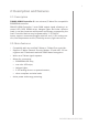
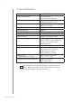


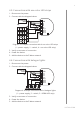
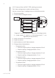
Table Of Contents

9
InstallatIon
4.3: Connection with one-color LED strips
1. Disconnect the power.
2. Connect with the diagram below:
12/24V DC
GND
IN3
IN4
OUT1
OUT2
OUT3
OUT4
IN1
GND
P
IN2
2
2
1
4
4
4
4
+
–
+
–
+
–
+
–
+
–
+
–
+
–
+
–
Diagram 3: Example connection with 4 one-color LED strips
(1 – power supply, 2 – switch, 4 – one-color LED strip)
3. Verify correctness of connection.
4. Power the device.
5. Add the device to the Z-Wave network.
4.4: Connection with halogen lights
1. Disconnect the power.
2. Connect with the diagram below:
12/24V DC
GND
IN3
IN4
OUT1
OUT2
OUT3
OUT4
IN1
GND
P
IN2
2
1
2
555
5
Diagram 4: Example connection with 4 halogen lights
(1 – power supply, 2 – switch, 3 – RGBW LED strip)
3. Verify correctness of connection.
4. Power the device.
5. Add the device to the Z-Wave network.