
User's Manual


A1471 User Manual
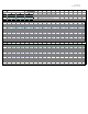
Setup Program BTR-700 Radios and Beltpacks to frequency groups as
indicated in System Connection Diagram. See appendix for BTR frequency charts
for reference. Set the transmitter RF output power for 100 mW. Be sure to
terminate the transmitter RF output before power up.
To install fiber optic cable to subrack, remove dust covers, clean optical
connector, align FC/APC connector key and hand tighten. Do not overtighten.
To install fiber optic cable to remote units, see attached fiber installation guide.
This guide is also provided on the inside lid label of remote units. Clean optical
connectors prior to installation.
To power up subrack and remote units, unsnap dust cover from power supply
receptacle and insert the provided power supply plug into the receptacle on the
unit. Align plug key, and push plug into receptacle. Tighten the locking ring on plug.
Power supplies are interchangeable between all units.
To remove optional 3dB attenuator from remote unit, refer to attached remote
unit diagram, or remote unit lid diagram. Remove power from remote unit. With
3/16” open end crescent wrench, loosen both ends of 3 dB attenuator from
attached RF cable and power amplifier. Remove attenuator, and directly re-connect
RF cable to power amplifier.
Installation Verification
Remote Transceivers To verify correct installation: LED’s L,M,N,O,and P should
all be green when the system is in normal operation. See Remote Transceiver
diagram for LED functions. This system has been designed to provide 20 mW of
RF power at each remote when the BTR-700 set to 100 mW. RF output power can
be increased 3dB by removing the optional 3dB attenuator. See Remote
Transceiver diagram for the location. Power must be removed from the unit before
this option is exercised.
Keep transmit and receive antennas separated 3 feet minimum. One antenna
extension kit is provided for each Remote Transceiver. DO NOT INSTALL
HARDWARE (ANTENNA OR POWER AMPLIFIER) TO BOOST RF OUTPUT
POWER. THIS MAY VIOLATE FCC RULES AND REGULATIONS.
Base Station Transceiver To verify correct installation: Verify system is
connected as shown in System Connection Diagram before power up. On the front
panel a Green LED will indicate that power is present in normal operation.
4 Maintenance
Precaution: All units should be handled observing ESD precautions to prevent
electro-static damages. Disconnect power prior to opening remote units.