
Installation Instructions


initial mark
3/4-in above
the mark
initial mark
3/8-in below
for upper
post
PRIOR TO INSTALLING STAIR BRACKETS:
Please consult local zoning laws in regards to load requirements, overall height requirements, and bottom space requirements for rails. All supporting structures must be in
accordance with applicable building codes. Neighborhood associations and/or historic districts may regulate size, type, placement and type of railing. Apply for permits if required by
local authorities and codes. Ensure compliance prior to installation. Local building code requirements will always supersede any and all suggested procedures and measurements in
the following installation. The following installation instructions are intended as a general guideline based on common building practices used in railing installation.
ELEMENTS
™
ALUMINUM STAIR BRACKET INSTALLATION
AL STR BKT 2PK BL
(3/8/18)
FIBERONDECKING.COM PAGE 1 OF 2
TOOLS REQUIRED
• Power drill
• 1/8-in drill bit for optional pilot hole pre-drilling
• Tape measure
• Screwdriver or power drill for T25 Torx screws
• Safety glasses
• Pencil
KIT CONTENTS
• (1) Top Rail End Cap & Backing Plate
• (1) Bottom Rail End Cap & Backing Plate
• (4) #10 x 3/4-in Torx Screws
• (6) #10 x 1/2-in Torx Screws
• (4) #12 x 2-in pan head Torx Screws (for wood post)
• (1) Instruction Sheet
TIPS
The most recent installation instructions can be found
on our website. Please visit www.fiberondecking.com
or call customer service at 800-318-7828.
Step 3: Install Top Stair Bracket
Measure up 30 1/8-in from the top of the installed
bottom backing plate and make a horizontal line
with a pencil onto the post (Figure 5). Locate the
BOTTOM edge of the backing plate along the
horizontal line. Take care to ensure the backing
plate is centered on the post, with the two
mounting holes lined up on top of each other).
Mark the center of the two mounting holes
located inside the backing plate against the post.
Optional: pre-drill the marked holes with a 1/8-in
drill bit.
Locate the backing plate over the marked or
pre-drilled mounting holes, and install two #10 x
3/4-in screws through the backing plate and into
the aluminum post. Do not overtighten screws.
NOTE: If installing into a wood post, install using
two #12 x 2-in pan head screws.
Slide the top rail end cap into the backing plate.
Secure with two #10 x 1/2-in screws through the
backing plate holes and into the top rail cap’s
pre-drilled holes (Figure 6). A third #10 x 1/2-in
screw is supplied to fill the end cap’s top
pre-drilled hole, if so desired.
Figure 6
Figure 5
Step 2: Install Bottom Stair Bracket
Locate the TOP edge of the backing plate for the bottom stair bracket along the
horizontal line. Take care to ensure the backing plate is centered on the post, with
the two mounting holes lined up on top of each other. Mark the center of the two
mounting holes located inside the backing plate against the post (Figure 2).
Optional: Pre-drill the marked holes with a 1/8-in drill bit.
Locate the backing plate over the marked or pre-drilled mounting holes, and install
two #10 x 3/4-in screws through the backing plate and into the aluminum post
(Figure 3). Do not overtighten screws.
NOTE: If installing into a wood post, install using two #12 x 2-in pan head screws.
STAIR BRACKET INSTALLATION
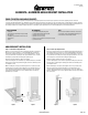
Step 1: Lay Out the Stair Posts and Stair Rails
For stair installation, loosely mount the stair posts and set out the stair rails. To
determine the stair bracket location, lay the bottom stair rail on top of the stairs/
nosing and, using the top of the bottom stair rail as a guide, make an initial mark
with a pencil onto the upper post and the lower post (Figure 1). From the mark you
made on the UPPER post (the post at the top of the stairs), measure and draw a
horizontal line 3/8-in below the mark. From the mark you made on the LOWER post
(the post at the bottom of the stairs), measure and draw a horizontal line 3/4-in
above the mark.
Figure 2
Figure 3
Figure 4
Slide the bottom rail end cap into the backing plate. Secure with two #10 x 1/2-in
screws through the backing plate holes and into the bottom rail cap’s pre-drilled
holes (Figure 4). A third #10 x 1/2-in screw is supplied to fill the end cap’s top
pre-drilled hole, if so desired.
30 1/8-in
Figure 1