
Installation Guide


Composite Railing systems are designed to work with a number
of different decking materials and surfaces. Before initiating any
project, obtain a copy of your local building codes and understand
them thoroughly. Local building code requirements will always
supersede any and all suggested procedures and measurements
in the following installation guidelines.
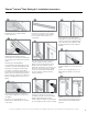
1. Shown is a 5
3
/
4
in. (175 cm) Post Sleeve over a wooden 4 in. x 4
in. (10 cm x 10 cm) using the new wood 4 in. x 4 in. (10 cm x 10
cm) adapters. Begin installation by drilling and securing the lower
4 in. x 4 in. (10 cm x 10 cm) Adapter roughly 1 in.-1
1
/
2
in. (3 cm
- 4 cm) off the deck surface. Make sure to use at least a 1
3
/
4
in.
(53 cm) long athead corrosion-resistant screw (Figure 1).
2. Secure the upper 4x4 Adapter positioned appropriately for the
required nished guardrail height (typically either 36 in. (91 cm)
or 42 in. (107 cm) from deck surface to top of top guardrail).
Placing the top of the 4 in. x 4 in. (10 cm x 10 cm) Adapter at
the desired nal guardrail height should align the center of the
Adapter with the Horizon Rail top bracket (Figure 2).
5. Position the bottom rail against the 5
3
/
4
in. (175 cm) Post with
the bottom bracket pre-assembled. Predrill holes through the
Sleeve, Adapter, and into the wood 4 in. x 4 in. (10 cm x 10
cm) post for the bracket fasteners (Figure 7A).
6. Secure bottom rail with supplied screws (Figure 7B-C).
7. Insert the outermost balusters and baluster daggers at
each end of the bottom rail. Position the top rail with the
preassembled bracket over the balusters and predrill for the
upper bracket fasteners through the Sleeve, Adapter, and into
the wood 4 in. x 4 in. (10 cm x 10 cm) post (Figure 8A).
8. Insert the remaining baluster daggers and balusters and
reposition the top rail. Secure with the supplied top bracket
screws (Figure 8B-C).
1 2
3 4 5
A
B
7
A B C
9 10
A B
8
A B C
C
7
The most recent installation instructions can be found on our website. Please visit berondecking.com or call Consumer and Technical Support at 800-573-8841.
5 3/4 in. (175 cm) Post Sleeve and Angled Rail Installation
3. After cutting to the desired length, slide the 5
3
/
4
in. (175 cm) Post
Sleeve over the wood 4 in. x 4 in. (10 cm x 10 cm) (Figure 3).
4. With the 5
3
/
4
in. (175 cm) Post Sleeve in place, position a 6 in.
(183 cm) Post Skirt followed by the 5-3/4 in. (175 cm) Cap/
Skirt Adapter. Glue the Cap/Skirt adapter in place with an
approved PVC or construction adhesive (Figure 4A). Post, Skirt
and Cap/Skirt Adapter in nal position (Figure 4B).
Note: The 5
3
/
4
in. (175 cm) Post Sleeve allows for a Horizon Rail
to be cut at a 45-degree angle and attached with the standard
brackets (Figure 5).
TIP: use two crush blocks or scrap lumber cut to the required
height to hold the bottom rail at and level.
9. Finish the application by placing a second Cap/Skirt Adapter
over the Post Sleeve (9A-B). Using an approved PVC or
construction adhesive, glue the cap in place and lift the Cap/
Skirt Adapter up to it for nal positioning (Figure 9C-10).