
Installation Guide
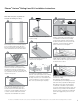
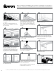
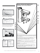
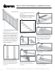
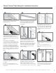
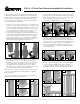
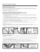
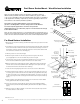

Figure 4
Fiberon Composite Railing systems are designed to work with a number of
different decking materials and surfaces. Before initiating any project, obtain a
copy of your local building codes and understand them thoroughly. Local building
code requirements will always supersede any and all suggested procedures and
measurements in the following installation guideline.
Kit Includes: (1) Surface Mount Bracket; (1) 4-in x4-in Wood Post;
(4) 1/4-in x 3-in Wedge-Bolt
™
Anchors; and (4) 5/16-in Fender Washers
For wood composite applications; consumers must purchase:
(4) Galvanized 5/16-in x 5-in Hex bolts; (3-6) #8 x 1-in Flat-head screws and (4)
5/16-in Galvanized Nuts
Note: To ensure proper fastening, it is recommended that the wood thickness be a
minimum of 4-in underneath the mount unless otherwise specied by local building
codes. For more detailed instructions visit us online at www.compositedeck.com.
For Wood Surface Installation:
1. Determine the desired location(s) and finished height of the post sleeve from the
deck surface.
2. The thickness of the wood/composite deck and reinforcement boards underneath
the deck should be a minimum of 4-in. (Two treated and structurally sound 2-in x
8-in lumber under the deck board, Fig 4). Fasten the reinforcement boards with
3-in stainless steel fasteners as shown (Fig 1).
3. Trim the post sleeve to desired length.
4. Trim the length of the 4-in x 4-in wood post insert if required. The wood
post is typically 1-in to 2-in shorter than the post sleeve length.
5. Use the base of the mount as a template and mark the four corner holes on
the deck surface. Mark inside square of bracket on the deck surface.
6. Drill four 3/8-in holes at the marked locations, drilling through the deck board
and the reinforcement boards. Drill a 3/8-in drainage hole in square through
deck board and reinforcement boards for drainage.
7. Locate the mount by aligning the mount corner holes over the drilled holes.
8. Insert the trimmed end of the 4-in x 4-in wood post (included) into the mount. If
necessary, place a shim under the mount to make the post plumb and true (Fig
2). If the wood post is loose within the mounting bracket, secure the wood post
on two opposing sides with at least (3) #8 x 1-in flat-head screws (Not included)
(Fig 3).
9. Insert a 5/16-in x 5-in galvanized hex bolt into the mount holes and the drilled
holes (galvanized bolts & nuts, Not included).
10. Secure the four bolts underneath the reinforcement boards with the 5/16-in
Fender washer (Included In Kit) and 5/16-in galvanized hex nuts (Not included)
(Fig 3).
11. Slide the post sleeve (Not included) over the 4-in x 4-in treated wood post until
it contacts the base of the mount.
Figure 2
4-in x 4-in
Wood Post
3.5-in
3.25-in
3.25-in
8.5-in
3.5-in
Trimmed end is inserted
into the post mount
Figure 1
2-in x 8-in
Reinforcement Boards
3-in Stainless
Steel Fasteners
(Not included)
Figure 3
Post Sleeve
(Not included)
4-in x 4-in
Wood Post
(Included)
Surface Mount Bracket
(Included)
Deck
Board
Inside
Square
5/16-in
Galvanized Nut
(Not included)
#8 x 1-in
at-head screws
(Not included)
5/16-in
Fender Washer
(Included)
VER-0018-LIT 6/14
5-in x 5/16-in
Galvanized Bolts
(Not included)
2-in x 8-in
(5 cm x 20 cm)
9
The most recent installation instructions can be found on our website. Please visit berondecking.com or call Consumer and Technical Support at 800-573-8841.
Post Sleeve SurfaceMount - Wood Surface Installation