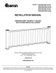
fiber on Model # SEC RW 8KD 335 AB SEGRE RW 6KD 33.5 AB SEC RWS 6HW 33.5AB SEGRE RW 8KD 39.5 AB SEC RW 6KD 38.5 AB SEC RWS 6HW 39.5AB INSTALLATION MANUAL ARMORGUARD® REGENCY” RAILING WITH ROUND METAL BALUSTERS Questions, problems, missing parts? Before returning to the store, call Fiber on Customer Service 8 a.m. 5 p.m., EST, Monday Friday 1-800-230-7547 FIBERONDECKING.COM THANK YOU We appreciate the trust and confidence you have placed in Fiber on through the purchase of this railing.
Table of Contents . Safety Information . Line Rail Installation Stair Railing Installation, Angle Bracket Installation , . Read and understand this entire manual before you begin the installation of your railing.
20 YEAR PERFORMANCE LIMITED WARRANTY WHAT IS COVERED This railing product is covered under a Limited Residential Warranty to protect against checking, splitting, decay, rot and splintering.
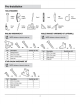
TOOLS REQUIRED Safety goggles 5/32 in. drill bit Rating bracket screw #0 x 1-1/4 in. screw Driver bit STAIR BAILING HARDWARE KIT NL #10 x Vin. resew #0 x 1-1/4 in.
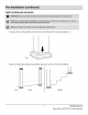
PRIOR TO INSTALLING THE RAILING wif using post sleeve molding, slide the post down into the cove molding prior Io securing any railings (Fig. 1). Fig. 1 FS] Fig. 2 For Line For Stairs 5 FIBERGNDECKING.COM Please contact 1-800-230-7547 for further assistance.
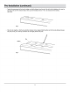
uw Transfer the measurement to the top rail, making sure that the distance from the end of the rail to the first baluster slot is equal on hotly ends of the rail. The minimum distance from a post to first baluster slot is 1-1/2 in. for clearance for the brackets. {Sea Fig. 3} Fig. 3 1 Place the rails together so that the top and bottom baluster slots are aligned. Mark the bottom rail for the inside distance between the posts {see Fig. 4), Gut the top and bottom rails to fit tightly between the posts.
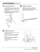
1 Preparing the bottom rail inset railing brackets (AA) 1/32 in. — 1116 in. from the ends of the bottom rail and mark the hole locations. Ensure the railing brackets (AA) are installed an the opposite side from the baluster holes. i Espadrille holes using a 5/32 in. bit and then atlas the railing brackets {AA} io the bottom rail using 1 in, screws (BB). D0 NOT OVER TIGHTEN THE SCREWS.
4 Preparing the top rail inset the raking brackets (88) 1/32 in. — 1/18 in. from the ends of the lop rail and mark the hole locations. Ensure railing brackets are installed on the side of the top rail with the baluster holes. i Espadrille holes using a 5/32 in. bit and then atlas the railing brackets {AA} io the top rail using 1 In. screws (BB). D0 NOT OVER TIGHTEN THE SCREWS. 5 Inserting balusters 3 Insert a baluster into the first and last baluster holes in the bottom rail.
8 Installing the balusters and top rail 9 Installing the post caps insert all balusters into the bottom rail. Reposition the 5 Complete the installation by installing the post cap in place. top rail over the balusters, and lower into place between You can use a quality exterior adhesive in order fo do this, the posts. After the top rail is fully sealed, secure using but note that you will not be able to remove the cap ata 1-1/4 bv, screws (CO). DO NOT TIGHTENER THE SCREWS. tater ime once it is glued.
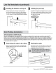
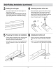
3 Cutting the rail angles 4 Attaching brackets to the rails 3 Gut the fop and bottom rails at the marked angles fo fit 3 Place brackets {6G} on each end of the bottom rail {side tightly between the posts. without baluster holes}. Place brackets on each end of 1 Transfer the stair angle to the crush block and cut to the the top rail {baluster hole side). Leave 1/32 in. desired length {consult your local building official for the space from the out edge of the rail.
7 Positioning the top rail insert a baluster info the first and last holes in the bottom rail. Carefully position the top rail over the balusters. Lower until the balusters are fully Inserted. 3 With the top rail fully seated, and using the top bracket as a guide, mark the [nation of the holes. Remove the rail before per-drifling the holes. grep 8 Drilling the top rail holes 5 Predicable the holes with 2 5/32 in.
Determining the angle of installation i Determine the angle of your installation using the supplied template and cut the template out along the appropriate marked fines. {You may wank to photocopy the template as & backup prior to culling), i Position the template on the non-routed, underside surface of the bottom rail. Mark the proper culling angle. Template will be reversed from the top rail. + Ensure baluster holes are equidistant from the end of rail fo ensure proper vertical alignment of balusters.
Questions, problems, missing parts? Before returning to the store, call Fiber on Customer Service 8 a.m. 5 p.m., EST, Monday Friday 1-800-230-7547 FIBERONDECKING.