
User's Manual


Reproduction forbidden without Fibocom Wireless Inc. written authorization - All Rights Reserved.
FIBOCOM N510-GL Hardware User Manual Page 33 of 56
Remarks:
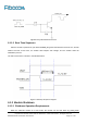
After the first POWER_ON power off, 4s is needed between the second POWER_ON power on
6.1.3 Reset
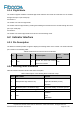
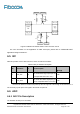
6.1.3.1 Reposition Pin Description
Table6-3 Reposition pin description
PIN
Pin Name
I/O
Pin Description
Power Domain
(TYP)
37
RESET
I
Reset signal
3.3V
6.1.3.2 Instructions for the Use of Reset
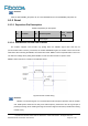
The module supports reset function. By pulling down the RESET signal more than 40 ms
(recommended value is 50 ms), over 60ms, the module will RESET again ,the module can be reset to the
initial state. After releasing the RESET, the module will restart. RESET can be suspended when not in use.
The low level voltage when pulling down RESET to start must be less than or equal to 0.5V.
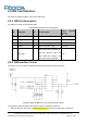
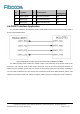
RESET control sequence is shown in the following figure:
Figure6-5 Reset control timing
Remarks:
RESET is a sensitive signal. It is recommended to add a de-jitter capacitor near the module
end. PCB layouts should be far away from radio frequency interference and do a good job of
packet processing, while avoiding the edge and surface alignment of PCB (to avoid ESD causing
module reset).