Chapter Software Functional Overview 3.1 Overview The M785 is an IBM PC/AT compatible Notebook PC which supports the Intel uFCPGA Socket Pentium IV processor family. The following are the major features that M785 supports. § Microsoft PC99 logo and WinXP logo approval. § 14.1" XGA / 15.1" XGA, SXGA+ panel support. § APM 1.2 compliance § Support ACPI 1.0B (or above). § Support PCI 2.2 (or above). § Support AGP 2.0. § Support USB 1.1, 2.0 § Support SMBIOS 2.3. § Support 400/533 Mhz CPU front side bus. 3.
Software Functional Overview Controller Chip Display Description § § § § Hard Disk System auto detects LCD or CRT presence on boot and lid closed Support Panning while LCD in a display resolution greater than supported Support Microsoft Direct 3D Support AGP 4x BUS § Enhanced IDE spec. § Support auto IDE detection. § Support LBA mode for larger capacity HDD. § Support Ultra DMA 33/66/100. § Support Fast PIO mode 1-4 transfer. § Support 32 bit PIO transfer. § Support Multi-Sector transfer.
Software Functional Overview 3.3 Subsystem Software Functions This section provides introduction on the software functions of the notebook subsystems and BIOS related function. 3.3.
Software Functional Overview 128MB 256MB 256MB 256MB 256MB 512MB 512MB 512MB 512MB 512MB NIL 128MB 256MB 512MB NIL 128MB 256MB 512MB 640MB 256MB 384MB 512MB 768MB 512MB 640MB 768MB 1024MB 3.3.3 Video The Video subsystem used External DDR memory of Video memory. The system will support the true ZV port, the Microsoft Direct 3D assist, simultaneous display, monitor sense for auto display on boot and VESA Super VGA function call. 3.3.
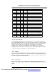
Software Functional Overview • Supported extended video modes CRT device will support all listed VESA mode; and other devices such as PANEL & TV may be limited to the mode support due to their characteristics CRT device will support all listed VESA mode; and other devices such as PANEL & TV may be limited to the mode support due to their characteristics.
Software Functional Overview VESA Mode 12Ch Pixel Resolution 1024 x 768 Memory Model 12Dh 12Eh 1280 x 1024 320 x 200 24-bit Packed 8-bit Packed Refresh Rates In (Hz) 43(I), 60, 70, 75, 85, 100 43(I), 60, 75, 85 70 131h 133h 320 x 200 320 x 200 8-bit Packed 16-bit Packed 72 72 2MB 2MB 134h 13Bh* 13Ch* 320 x 200 1400 x 1050 1400 x 1050 32-bit Packed 8-bit Packed 16-bit Packed 72 60, 75 60, 75 2MB 2MB 4MB 13Eh* 141h 1400 x 1050 400 x 300 32-bitUnpacked 60, 75 8-bit Packed 72 8MB 2MB 143h 1
Software Functional Overview GPI[45] GPI[46] GPI[10] GPI[22] 0 0 0 0 0 0 0 0 1 1 1 1 1 1 1 1 0 0 0 0 1 1 1 1 0 0 0 0 1 1 1 1 0 0 1 1 0 0 1 1 0 0 1 1 0 0 1 1 0 1 0 1 0 1 0 1 0 1 0 1 0 1 0 1 Panel Type LTN141X8-L04 (Samsung) B141XN04V2 (AU) LTN150U1-L02 (Samsung) LTN150P3-L04 (Samsung) 3.3.5 Enhanced IDE The system BIOS must be ready to support 4 IDE devises on two controllers.
Software Functional Overview 3.3.7 PCMCIA The PCMCIA controller chip of the notebook provides the following features: • • • 3.3.8 Support for only single CardBus slot (two type II stacked) Individually accessed, dual-buffer implementation Support for 3.3v, 5v and 12v (flash programming) cards LED Indicator The table below lists down the functions of the Status LED indicator: Indicator Function Description IDE accessing LEDŒ This LED will turn on while accessing the IDE Device.
Software Functional Overview 3.3.10 Plug & Play The BIOS supports the Plug and Play Specification 1.0A. (Include ESCD) This section describes the device management.
Software Functional Overview • PCI Device The table below summarizes the PCI IDSEL Pin Allocation: PCI Device Device Number Function Number AD11 Device 00 Function 0 SISM650 - Host to PCI bridge AD12 Device 01 Function 0 SIS962 – PCI to PCI bridge AD13 Device 02 Function 0 SIS962 - PCI to ISA bridge Function 2 SIS962 - ADSL (Not support) Function 3 SIS962 - 1394 Function 4 SIS962 - PMU and SMBus interface Function 5 SIS962 - IDE interface Function 6 SIS962 - AC97 Modem interface Fu
Software Functional Overview 3.3.11 MBus Devices The SMBus is a two-wire interface through which the system can communicate with powerrelated chips. The BIOS should initialize the SMBus devices during POST.
Software Functional Overview Hex Address 0C0 – 0DF 8237-2 0F0 – 0FF Math Coprocessor 170 – 177 Secondary IDE Controller 1F0 – 1F7 Primary IDE Controller 200 – 20F Game Port 220 – 22F Sound Blaster 279 MIDI 370 – 371 Sound chip control port 378 – 37A Parallel Port 388 – 38B FM Synthesizer 398 – 399 Super I/O Chip 3B0 – 3DF Video Controller 3E0 – 3E1 PCMCIA Controller 3E8 – 3EF Fax/Modem 3F0 – 3F7 Floppy Disk Controller 3F8 – 3FF Serial Port 1 530 – 537 Microsoft Sound System
Software Functional Overview D0000 ~ DFFFFh E0000 ~ FFFFFh l 16 KB 128 KB DMI information System ROM BIOS IRQ Map IRQ# IRQ 0 Description System Timer Keyboard [Cascade] PHS (Serial) Serial Port Audio/VGA/USB Floppy Disk Drive Parallel Port RTC Alarm Reserved for PCMCIA card LAN / Modem or Combo, (Card Bus), IEEE 1394 ACPI PS/2 Mouse FPU (FERR) Hard Disk Drive CD-ROM or DVD-ROM IRQ 1 IRQ 2 IRQ 3 IRQ 4 IRQ 5 IRQ 6 IRQ 7 IRQ 8 IRQ 9 IRQ10 IRQ11 IRQ12 IRQ13 IRQ14 IRQ15 3.
Software Functional Overview GPIO Number GPIO7 Default I/O EC_SCI0 1 I GPIO8 PM_RI0 1 I GPIO9 GPIO10 N.C. MB_ID1 -1 -I GPIO11 PM_SLP_S10 1 O GPIO12 STPCPU0 1 O GPIO13 GPIO14 GPIO15 N.C. SPDMUX0 N.C.
Software Functional Overview PIN Signal I/O GPIOB5 N.C. PM_SLP_S 1# PM_RI# N.C. N.C. CHGLED N.C. X GPIOB6 GPIOB7 GPIOC0 GPIOC1 GPIOC2 GPIOC3 Normal I SIS962 O X X O X SIS962 Runtime / Wake event Low = POS, STR and STD suspend state Low = Wake Up Event (SMI or SCI) Charge LED High = Turn ON Charge LED I : INPUT O : OUTPUT L-Lever : Low Lever H-Lever : Hi Lever Function Pin Description : A : A-D Converter Input Pin 3.4.
Software Functional Overview Port PORT 5 PORT 6 PORT 7 i 3-16 Pin Name P57 P56 P55 P54 In/Out OUT OUT IN IN Description NC NC GPRS_PWRENA GPRS_VDDPD P50 P61 P60 P62 P63 P64 P65 P66 P67 P70 P73 P72 P75 P74 P71 P76 P77 OUT IN IN IN IN OUT IN OUT OUT I/O I/O I/O I/O I/O I/O I/O I/O ISA ADDRESS (SA2) KBSEL2 KBSEL1 GPRS_ON/OFF LOGSEL PASS0 NC BT_FETON1 BT_SENSE0 PS2 DATA PS2 CLOCK EXTERNAL KB DATA EXTERNAL KB CLOCK EXTERNAL MOUSE CLOCK EXTERNAL MOUSE DATA SMDAT_KBC SMCLK_KBC I : INPUT O : OUTPUT FIC
Software Functional Overview 3.5 Power Management This section provides the Power Management software function of the notebook. 3.5.1 General Requirements The BIOS meet the following general Power Management requirements: • • • • • • • • • • 3.5.2 Compliant with ACPI 1.0B / ACPI 2.
Software Functional Overview l Stand by mode A suspend state where all motherboard components are still powered-on except for the system clock generator device. The PCI and CPU buses are driven to the inactive idle state. The system memory is powered and refreshed by the memory bridge, and the graphics frame buffer is powered and refreshed by the graphic chip. The system provides a 32Khz clock (SUSCLK) in this suspend mode to support refresh of these memory subsystems.
Software Functional Overview 3.5.4 Power Management Mode Transition Flow S1 Sleeping Wake Event SLP_TYPx=S2 and SLP_EN ACPI Boot (SCI_EN=1) G2 (S5) Soft Off G0 (S0) Working SLP_TYPx=S5 and SLP_EN or PWRBTN_OR SLP_TYPx=S1 and SLP_EN S4BIOS_REQ to SMI_CMD OEM S4 BIOS Handler SLP_TYPx=S3 and SLP_EN SLP_TYPx=S4 and SLP_EN S2 Sleeping G1 S3 Sleeping S4 Sleeping SLP_TYPx=S4 and SLP_EN FIC M785 Service Manual PDF created with FinePrint pdfFactory Pro trial version http://www.pdffactory.
Software Functional Overview 3.5.5 Power Management Mode Transition Event The following table summarizes the entry events and wake-up events of each power Power State Entry Event Wake up Event S1 OSPM control Power Button Lid Close Ring Indicator Battery Low - Low RTC Alarm LAN Wake Up S4 OSPM control, Power Button STD hot key pressed RTC Alarm Lid Close Battery Low – Low S5 Power Button Power Button Execute Windows shutdown RTC Alarm command 3.5.
Software Functional Overview PMU08 VGA/VRAM PCMCIA Super I/O AUDIO Audio AMP LCD Backlight Serial Port IR Module LAN Internal Modem l ON ON ON ON ON ON ON ON ON ON ON ON Power Down Power Down Power Down Power Down Power Down Power Off Power Down Power Down Power Down Power Down Power Down Power Down Power Down Power Off Power Off Power Off Power Off Power Down Power Off Power Down Power Down Power Down Power Off Power Off Power Off Power Off Power Off Power Off Power Off Power Off Power Down Power Down
Software Functional Overview l Device PM control during STR mode Device Power Down Controlled by Description CPU L2 CACHE SIS962 DRAM Clock Synthesizer CDROM HDD FDD (M785 Not support) KBC Hardware Hardware Hardware Software Hardware Hardware Hardware Hardware Controlled by SUSB# pin Power off Controlled by SUSB# pin Self Refresh Controlled by SUSB# pin Power off Power off Power off Software PMU08 VGA/VRAM PCMCIA Super I/O AUDIO Audio AMP LCD Backlight Serial Port IR Module LAN Sofeware Software So
Software Functional Overview 3.6.1 Expanding Event Through the Embedded Controller The following figure shows the relationships between the devices that are wired to the embedded controller, the embedded controller queries, and ACPI general FIC M785 Service Manual PDF created with FinePrint pdfFactory Pro trial version http://www.pdffactory.
Software Functional Overview l SCI Source and Query Event from M38867 PMU08 ADPIN# BAT0# GPIOA0 GPIOA3 GPIOA6 GPIOA7 THRM Input Event GPE Event Handler AC Plug In/Out Battery Plug In/Out LID Event Keyboard SMI PCMCIA Ring In COM Port Ring In Thermal Event GPI1 GPI1 RI RI RI RI GPI1 AML Handler AML Handler AML Handler AML Handler AML Handler AML Handler AML Handler The system will issue a beep to inform user while the following SCI alerted: § AC (AC status change) update battery information.
Software Functional Overview 3.6.2 Thermal Control There are three primary cooling policies that the OS use to control the thermal state of the hardware. Cooling Policy Action cooling Action cooling Action Fan On Fan High On Fan High Off Passive cooling Throttling CPU On Throttling CPU Off Critical trip point System Shutdown Temperature Setting Always On Over 55oC Below 50oC Over 70oC Below 60oC Over 80oC ACPI allows OS to be proactive in its system cooling policies.
Software Functional Overview anticipate _ACx, PSV, or _CRT events and incorporate heuristics to better manage the systems temperature.The operating system can request that the hardware change the priority of active cooling vs passive cooling. l Dynamically Changing Cooling Temperatures An OEM can reset _ACx and _PSV and notify the OS to reevaluate the control methods to retrieve the new temperature settings.
Software Functional Overview 1. When the heat increases to the temperature designated by _ACx, the OS will turn on the associated active cooling device and the hardware will reset the ACx value to a lower temperature. 2. The hardware will then run the Notify command and the OS will reevaluate the new temperatures. Because of the lower _ACx value now, the fan will be turned off at a lower temperature than when turned on. 3.
Software Functional Overview • If the zone uses two independently-controlled single-speed fans to regulate the temperature, then _AC0 will evaluate to the maximum cooling temperature using two fans, and _AC1 will evaluate to the standard cooling temperature using one fan. If a zone has a single fan with a low speed and a high speed, the _AC0 will evaluate to the temperature associated with running the fan at high-speed, and _AC1 will evaluate to the temperature associated with running the fan at low speed.
Software Functional Overview 3.6.6 Critical Shutdown When the heat reaches the temperature indicated by _CRT, the OS must immediately shutdown the system. The system must disable the power either after the temperature reaches some hardware-determined level above _CRT or after a predetermined time has passed. Before disabling power, platform designers should incorporate some time that allows the OS to run its critical shutdown operation.
Software Functional Overview 3.6.8 Thermal Control Methods Control methods and objects related to thermal management are listed in the table below.
Software Functional Overview 300.0K are represented by the integer 3000. l _PSL This object evaluates to a list of processor objects to be used for Passive cooling. l _PSV This control method returns the temperature at which the OS must activate CPU throttling. Arguments: None. Result Code: Temperature in tenths Kelvin. The result code is an integer value that describes up to 0.1 precision in Kelvin. For example, 300.0 Kelvin is represented by 3000.
Software Functional Overview 3.6.9 AC Adapters and Power Source Objects The Power Source objects describe the power source used to run the system. Object Description _PSR Returns present power source device _PCL List of pointers to powered devices. l _PSR Returns the current power source devices. Used for the AC adapter and is located under the AC adapter object in name space. Used to determine if system is running off the AC adapter.
Software Functional Overview 3.7.4 AC Adapter When plug in the AC adapter, the system will do the following action: - The charger will charge the Main Battery, if remaining capacity is not full. - The Battery Charging Indicator will turn on if the battery is in changing mode. 3.8 PMU08 The embedded controller PMU08 acts as a supplement for power management control. It supports a lot of functions via SMBus interface. 3.8.
Software Functional Overview Function Address 00h *3 02h *3 04h *3 08h *3 Design Voltage Design capacity of Warning Design capacity of Low Battery capacity Granularity 1 Battery capacity Granularity 2 Model number Serial Number 0Eh *3 3-34 Design capacity Last Full Charge Capacity Battery Technology 0Ch *3 *1: *3: R(/W): Power unit 06h *3 0Ah *3 1st Battery [ _BIF ] Register Name 10h *3 12h *3 14h *3 R/W 7 Bit Number Logic Default Description 6 5 4 3 2 1 0 0x0000: mWh [Fixed value] 0xffff: U
Software Functional Overview Function Address 1Ah *3 1st Battery [ _BST ] 1Ch *3 1Eh *3 20h *3 1st Battery [ _BTP ] 22h 2nd Battery [ _BIF ] 24h to 3Ch *3 3Eh to 44h *3 2nd Battery [ _BST ] 2nd Battery [ _BTP ] - The battery is discharged DCHG=1: The battery is CHG =1 : charged CRIT =1 : The battery is critical (Empty) 0x0000-0xfffe(mW) 0xffff 0xffff: Unknown - R(/W) DATA[15:0] *1 - R(/W) DATA[15:0] *1 - 0xffff 0x0000-0xfffe(mWh) 0xffff: Unknown R(/W) DATA[15:0] *1 - 0xffff 0x0000-0xff
Software Functional Overview Function Address 6Ch PMU Access Reserved *7: R(/W): 3-36 R/W Bit Number Logic Default Description 7 6 5 4 3 2 1 0 R/W DATA [7:0] - - R/W DATA [15:8] - - R/W DATA [7:0] - - 6Fh PMU_DATA R/W DATA [7:0] - - 70h *7 SMB_PTCL R/W PROTOCOL[7:0] - - - - 6Dh 6Eh 71h *7 SMBus Register Name PMU_LOW_ ADR PMU_HIG_ ADR CHECK_ SUM SMB_STS R/W 72h SMB_ADDR R/W 73h SMB_CMD 74h to 93h SMB_DATA R/W [0-31] 94h SMB_BCNT R/W 95h SMB_ ALARM_ ADDR R(/W) 96
Software Functional Overview Function Address R/W A0h *3 ADP_STS A1h *3 BAT1_STS R(/W) (1st Battery) A2h *3 A3h *3 A4h *3 A5h *3 A6h *3 Status Register Name R(/W) Bit Number 7 6 5 4 3 2 1 0 C RES[7:1] O N DeDescription fault - - - - - - Don’t care - - BAT1_CAP R(/W) BCAP - - BAT2_CAP R(/W) BCAP - - Don’t care - - BAT2_STS R(/W) (2nd Battery) Reserved Reserved D B E L W E C C C T M O A R H O H P P W R R G N G R/W R/W A7h SMB_Alert_ R/W ADDR A8h *5 A9h *5 GPIO-A_ EVT_
Software Functional Overview Function Address B0h Event/ GPIO Control *4: 3-38 Register Name EC_RUN_ ENB R/W R/W B1h EC_WAKE_ ENB B2h BATT_RUN_ R/W ENB R/W Bit Number 7 6 5 4 3 2 1 0 B A S T L M P R B 2 T RES[4:1] A D P B E L W E C C C T M O A R A / O P P W R R P D N B3h BATT_WAKE R/W _ENB B4h GPIO-A_ IO_CONF R/W CONF_A [7:0] B5h GPIO-A_ DATA R/W DATA_A [7:0] B6h GPIO-A_ RUN_ENB R/W RUN_ENB_A [7:0] B7h GPIO-A_ EVT_POL R/W POL_A [7:0] B8h GPIO-A_ WAKE_ENB R/W WAKE_ENB_A
Software Functional Overview Function Address Register Name R/W C0h GPIO-C_ EVT_POL R/W C1h GPIO-C_ WAKE_ENB R/W Bit Number 7 6 5 4 3 2 1 0 Logic 0: Falling POL_ edge C 0 0 0 0 0 0 1: [1:0] Rising edge WAK 0: E_ Disable 0 0 0 0 0 0 ENB 1: _C Enable [1:0] DeDescription fault 0x00 0x00 WAKE SCI C2h EVT_CONT R/W Q W R _ RES S E R A C K S U [7:6] I N E *4 W A K E _ O U T Q_RU N S U S _ X 0x00 WAKE _OUT Event/ GPIO Control SUS_X C3h EC_RUN_ ENB_2 R/W Reserved [7:1] C4h C5h To C7h C
Software Functional Overview Function Address D0h BAT_CHG_ CONT R/W R/W Bit Number 7 6 5 4 3 2 C H G _ RES RES[7:5] R [3:2] D Y # 1 0 C H G 2 C H G 1 - BAT_DCH_ PRI D2h BAT_DCH_ CONT R/W RES[7:2] D3h BAT_WAR_ ABS R/W DATA[15:0] *1 - D5h BAT_LOW_ ABS R/W DATA[15:0] *1 - D7h BAT_WAR_ REL R/W DATA [7:0] - D8h BAT_LOW_ REL R/W DATA [7:0] - D9h *3 FULL_DATA R/W DATA [7:0] - Dah CC_CUR_ DATA R DATA [7:0] - DBh To DCh BTP2 R/W DATA [15:0] - DDh To DFh Reserved R/W
Software Functional Overview Function Address E0h Register Name PMU_CONT R/W R/W Bit Number 7 6 5 4 3 2 1 0 RES[7:3] E C _ R E G B A Y _ L E D PMU control E1h ACPI_ACC_ ENB R/W RES [7:1] E2h OFF_TIME R/W DATA [7:0] E3h POLLING_ ADDRESS R/W E4h E5h HIGH_ ALARM LOW_ ALARM Slave Address [6:0] R/W DATA [7:0] R/W DATA [7:0] Logic P O W _ L E D - O S _ S T S - R E S Signed value Signed value E6h POLLING_ INTERVAL R/W DATA [7:0] E7h POLLING_ DATA R(/W) DATA [7:0] Signed va
Software Functional Overview 3.9 Miscellaneous 3.9.1 Power Button The system may have different action upon pressing the Power Button when the system is in the different state. System Power State Full-on Stand by STR STD SOff/MOff 3.9.2 Action for Pressing Power Button Power Off Power Off Resume from STR Resume from STD Power On Security The user may enter up to 8 standard text characters for a password. The password includes two levels. The higher priority is the Supervisor Password.
Software Functional Overview supporting a wider bus (32 bits instead of 16 bits), CardBus also supports bus mastering and operation speeds up to 33MHz. Clock Throttling – South bridge function that allows the CPU clock to be stopped and started at a known duty cycle using the STPCLK# pin to enter and exit Stop Grant mode. Clock throttling is used for power saving, thermal management, and reducing the processing speed. DIMM (SODIMM) - Dual In-line Memory Module, a small circuit board that holds memory chips.