Chapter Software Functional Overview 3.1 Overview The MD02 is an IBM PC/AT compatible Notebook PC, which supports the Intel MicroPGA Pentium M CPU processors family. The following are the major features that MD02 supports. § Microsoft PC99 logo and Win XP logo approval. § Offer 1024x768 XGA display with 13.3 XGA LCD panel. § Support ACPI 1.0B (or above). § Support PCI 2.1 (or above). § Support AGP 2.0. § Support SMBIOS 2.3. § Support DDR266/200 SDRAM. § Support 100/133 Mhz CPU front side bus. 3.
Software Functional Overview Hard Disk Multi Boot Plug and Play Smart Battery Keyboard Controller PCMCIA Power Management Support (ACPI Mode) 3.3 § Enhanced IDE spec. § Support auto IDE detection. § Support LBA mode for larger capacity HDD. § Support Ultra DMA 33/66/100. § Support Fast PIO mode 1-4 transfer. § Support 32 bit PIO transfer. § Support Multi-Sector transfer. § Support SMART monitoring.
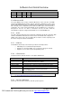
Software Functional Overview 3.3.2 System Memory The system memory consists of SDRAM memory on 64-bit bus and the module size options are 128/256/512/1GMB upward. The BIOS will automatically detect the amount of memory in the system and configure CMOS accordingly during the POST (Power-On Self Test) process. This must be done in a way that requires no user interaction.
Software Functional Overview 0Eh 640*200 16 4-bit Planar 0Fh 640*350 Mono 1-bit Planar 10h 640*350 16 4-bit Planar 11h 640*480 2 2-bit Planar 12h 640*480 16 4-bit Planar 13h 320*200 256 8-bit Planar Note: All Standard VGA Modes are limited to the standard VGA refresh rates. Supported extended video modes: CRT device will support all listed VESA mode; and other devices such as PANEL & TV may be limited to the mode support due to their characteristics.
Software Functional Overview 134h 320 x 200 32-bit Packed 72 2MB 13Bh* 1400 x 1050 8-bit Packed 60, 75 2MB 13Ch* 1400 x 1050 16-bit Packed 60, 75 4MB 13Eh* 1400 x 1050 32-bitUnpacked 60, 75 8MB 141h 400 x 300 8-bit Packed 72 2MB 143h 400 x 300 16-bit Packed 72 2MB 144h 400 x 300 32-bitUnpacked 72 2MB 151h 512 x 384 8-bit Packed 70 2MB 153h 512 x 384 16-bit Packed 70 2MB 154h 512 x 384 32-bitUnpacked 70 2MB 171h 720 x 480 8-bit Packed 75 2MB 173h 720 x
Software Functional Overview 1 1 0 1 1 1 1 0 1 1 1 1 3.3.4 Enhanced IDE The system BIOS must be ready to support 4 IDE devises on two controllers. The BIOS support Ultra DMA33/66/100 and also supports automatic configuration of drives using both the LBA and CHS large drive remapping method. In addition to supporting standard drives through an auto-configuration process that does NOT require user involvement or confirmation.
Software Functional Overview Function Function Handler Fn + F3 Toggle Display (LCD/CRT/TV/LCD&CRT) BIOS Handler Fn + F2 RF ON/OFF BIOS Handler Fn + F6 Fn + F8 Fn + F9 ScrLock Internet Button Mail Button System Speaker On/Off Brightness Increase Brightness Decrease Scroll Lock Internet Function Key BIOS Handler Controlled by PMU08 Controlled by PMU08 Mail Function Key Controlled by Driver Controlled by Driver 3.3.10 Plug & Play The BIOS supports the Plug and Play Specification 1.0A.
Software Functional Overview IDSEL Pin PCI Device Number AD23 Device 07 AD17 Device 01 Device Function Number Function 0 Function 1 Function 0 Device Name RICOH Card Bus RICOH IEEE1394 MINI PCI The table below summarizes the INT Pin Allocation: INT Pin INTA INTB INTC INTD PCI Device CardBus/MiniPCI/LAN Cardbus/MiniPCI The table below summarizes the PCI bus master Allocation: Arbiter Signal Agents (Master) Function Use REQ00/GNT00 REQ10/GNT10 RICOH Card Bus Controller REQ20/GNT20 REQ30/GNT3
Software Functional Overview I/O Map Hex Address 000 - 01F 020 - 021 022 040 - 05F 060 - 064 068 – 06C 070 - 07F 080 - 08F 092 0A0 - 0A1 0B2 0B3 0C0 – 0DF 0F0 – 0FF 170 - 177 1F0 - 1F7 220 - 22F 279 330 - 333 376 388 - 38B 3B0 - 3DF 3E0 - 3E1 3F0 - 3F5, 3F7 3F6 A79 CF8 – CFF Device 8237-1 8259-1 8254 Keyboard Controller PMU08 Controller RTC & NMI Mask DMA Page Registers System Control Port 8259-2 Advanced Power Management Control Port Advanced Power Management Status Port 8237-2 Math Coprocessor IDE Second
Software Functional Overview IRQ Map IRQ# IRQ 0 IRQ 1 IRQ 2 IRQ 3 IRQ 4 IRQ 5 IRQ 6 IRQ 7 IRQ 8 IRQ 9 IRQ10 IRQ11 IRQ12 IRQ13 IRQ14 IRQ15 Description System Timer Keyboard Audio/VGA/USB Floppy Disk Drive RTC Alarm ACPI LAN / Modem or Combo, (Card Bus), IEEE 1394 Reserved for PCMCIA card Glide Pad FPU (FERR) Hard Disk Drive CD-ROM or DVD-ROM 3.3.13 GPIO Pin Assignment The GPI and GPO pins connected to system devices. The BIOS can get device’s status and control the device via the GPI and GPO pins.
Software Functional Overview 3.3.14 PMU08 GPIO pin assignment GPIO number GPIO B6 Signal Default I/O Name PM_SLP_S 1 I 10 GPIO B5 N.C. -- -- Suspend Plane A control for ICH4 0: POS, STR and STD suspend state. 1: not suspend state. No used GPIO B4 N.C. -- -- No used GPIO B1 N.C. 1 O No used GPIO B0 GPIO A7 GPIO A6 N.C. N.
Software Functional Overview Global System State Definitions Global system states (Gx states) apply to the entire system and are visible to the user. Following is a list of the system states: G0/S0 - Working: A computer state where the system dispatches user mode (application) threads and they execute. In this state, devices (peripherals) are dynamically having their power state changed.
Software Functional Overview complete boot when awakened. Software uses a different state value to distinguish between the S5 state and the S4 state to allow for initial boot operations within the BIOS to distinguish whether or not the boot is going to wake from a saved memory image. System Power Plane The system components are grouped as the following parties to let the system to control the On/Off of power under different power management modes. 3.4.
Software Functional Overview S1 Sleeping Wake Event SLP_TYPx=S1 and SLP_EN SLP_TYPx=S2 and SLP_EN ACPI Boot (SCI_EN=1) G2 (S5) Soft Off G0 (S0) Working SLP_TYPx=S5 and SLP_EN or PWRBTN_OR S4BIOS_REQ to SMI_CMD OEM S4 BIOS Handler 3.4.
Software Functional Overview system under each power management mode.
Software Functional Overview Lid Switch (Cover Switch) The function of Lid Switch is depends on the ACPI aware OS. 3.4.
Software Functional Overview Control Method Battery Subsystem EC should support all the battery information to ACPI-OS − Designed Battery capacity − Designed Voltage − Designed Low battery capacity − Designed Low – Low battery capacity − Latest Full charged capacity − Present Remaining capacity − Present drain rate − Present voltage − Present Battery Status ACPI BIOS should support an independent device object in the name space, and implement the following methods. 3.4.
Software Functional Overview 2) The system will issue a Warning beep. 3.5.3 Battery Low - Low When the battery voltage is approaching to the Low-Low level, the PMU08 will generate a battery low-low SMI. The system will do the following action. 1) The Power Indicator will keep on Blinking. 2) The system will enter Suspend To Disk mode even the power management is disabled. The function of power-on or Resume will be inhibited until the battery Low – Low condition is removed. 3.5.
Software Functional Overview #3 EC_DAT A W Data to write Interrupt on IBF=0 #1 EC_SC W Command byte Header No Interrupt #2 EC_DAT A R Burst acknowledge byte Interrupt on OBF=1 0x83 #1 EC_SC W Command byte Header Interrupt on IBF=0 0x84 #1 EC_SC W Command byte Header No Interrupt #2 EC_DAT A R Query value to host Interrupt on OBF=1 0x82 Burst Enable Embedded Controller (BE_EC) Burst Disable Embedded Controller (BD_EC) Query Embedded Controller (QR_EC) 3.6.
Software Functional Overview Functio Address n Bit Number Logic Default Description 7 6 5 4 3 2 1 0 0Ah *3 Design capacit R(/W) y of Warnin g DATA[15:0] *1 - 0xffff 0x0000-0xfffe(mWh) 0xffff: Unknown 0Ch *3 Design capacit R(/W) y of Low DATA[15:0] *1 - 0xffff 0x0000-0xfffe(mWh) 0xffff: Unknown 0Eh *3 Battery capacit R(/W) y Granul arity 1 DATA[15:0] *1 - 0xffff 0x0000-0xfffe(mWh) 0xffff: Unknown 10h *3 Battery capacit R(/W) y Granul arity 2 DATA[15:0] *1 - 0xffff 0x0000-0xfffe(mWh
Software Functional Overview Functio Address n 18h *3 Functio Address n st 1 Battery [ _BST ] Regist er R/W Name Bit Number DATA [15:8] OEM Inform R(/W) *1 ation All bits are 0 Regist er R/W Name Logic Default Description 7 6 5 4 3 2 1 0 Vender [7:0] Bit Number - Vender [7:0] This code depends on battery data format. And the following name should be described in the ASL with the same character code. In the future, these codes will be added.
Software Functional Overview Functio Address n Regist er R/W Name Bit Number Logic Default Description 7 6 5 4 3 2 1 0 *3 nd 2 Battery [ _BST ] 3Eh to 44h *3 *2 *2 *2 *2 *2 *2 46h *2 *2 *2 *2 *2 *2 0x01: DATA size is 3byte.(PMU06A) 0x00: DATA size is 2 byte. (PMU06) *8 nd 2 Battery [ _BTP ] - 48h Battery R data (/W) Size DATA [7:0] - - 49h Design R capacit (/W) y DATA [23:16] *1 *7 - 0xff PMU06A use this data with 02/03h.
Software Functional Overview Functio Address n 51h to 6Bh *3 Functio Address n SMBus Bit Number Reserv R/W ed Regist er R/W Name Logic Default Description 7 6 5 4 3 2 1 0 Don’t care - Bit Number - Logic Default Description 7 6 5 4 3 2 1 0 PMU_L OW_ R/W ADR DATA [7:0] 6Dh PMU_ HIG_ R/W ADR DATA [15:8] - - 6Eh CHEC K_ R/W SUM DATA [7:0] - - 6Fh PMU_ R/W DATA DATA [7:0] - - 70h *7 SMB_ R/W PTCL PROTOCOL [7:0] - - 71h *7 SMB_ R/W STS - - 72h SMB_ R/W ADDR ADDRESS [6:0] -
Software Functional Overview Functio Address n Reserv ed 98h SMB_ R/W CNRL 99h to 9Fh Reserv R/W ed Functio Address n SMBus 3-24 Regist er R/W Name Bit Number Logic Default Description 7 6 5 4 3 2 1 0 RES [7:1] P R T Don't care 0x00 - Bit Number PRT =1: TheSMBus address (A8AE) protection is cancelled.
Software Functional Overview Functio Address n 96h to 97h Reserv ed Regist er R/W Name AMB_ ALAR R M_ (/W) DATA [0-1] 98h SMB_ R/W CNRL 99h to 9Fh Reserv R/W ed Function Addr Register R/W ess Name Status A0h ADP_ST R(/W ) *3 S Bit Number Logic Default Description 7 6 5 4 3 2 1 0 DATA RES [7:1] - P R T Don't care 0x00 - Bit Number 7 6 5 4 3 2 1 0 RES [7:1] - C O N BAT1_ST A1h S R(/W ) *3 (1st Battery) PRT =1: - Logic Defau Description lt - - D B E L WE C C C T MO A R H O H BAT
Software Functional Overview Function Addr Register R/W ess Name Bit Number 7 6 5 4 3 2 1 0 Logic A5h BAT2_C R(/W ) *3 AP BCAP - - A6h Reserve R/W *3 d Don’t care - - SMB_Ale A7h rt_ R/W ADDR ADDRESS[6:0] GPIO-A_ A8h EVT_ST R/W *5 S STS_A [7:0] GPIO-B_ A9h EVT_ST R/W *5 S GPIO-C_ AAh EVT_ST R/W *5 S R E S - Read 0:No event 1:EVT 0 STS_B [6:0] detection Write STS 0:Clear event 0 0 0 0 0 0 _C 1:Ignore [1:0] B S A G R B B A Read RUN_ ABh EVT_ST R/W T M L P E A A D 0:No event *5 S P B R I S
Software Functional Overview Function Addr Register R/W ess Name Bit Number 7 6 5 4 3 2 1 0 2 T O Logic detection Write 0:Clear event 1:Ignore 2 1 WAKE_ ACh EVT_ST R/W *5 S 0x00 RUN_ ADh EVT_ST R/W *5 S_2 Reserved [7:1] T H WAKE AEh EVT_ST R/W *5 S_2 Reserved [7:1] T H AFh THERMA L_EVT_S R/W *5 TS Event/ EC_RUN R/W GPIO B0h _ ENB Control EC_WAK R/W B1h E_ ENB Defau Description lt Reserved [7:3] H E L I R O G R W H 0: Disable B A S A 1: Enable T L RES[4:1] M D P R B P 0: Disable 2 T 1: Ena
Software Functional Overview Function Addr Register R/W ess Name Bit Number 7 6 5 4 3 2 1 0 BATT_R R/W B2h UN_ ENB BATT_W R/W B3h AKE _ENB B E L WE C CC T MO A R A / O P P W R R P D N 0: Disable 1: Enable CONF_A [7:0] GPIO-A_ R/W DATA DATA_A [7:0] GPIO-A_ B6h RUN_EN R/W B 0: Input 1: Output Defau Description lt 0x00 BTP: EMP: LOW: WAR: ERR: 0x00 CAP: C/D: CON: 0: Disable 1: Enable 0x00 GPIO-A_ B7h EVT_PO R/W L POL_A [7:0] 0: Falling edge 1: Rising edge 0x00 GPIO-A_ B8h WAKE_E R/W NB WAKE
Software Functional Overview Function Addr Register R/W ess Name GPIO-C_ BFh RUN_EN R/W B Event/ GPIO-C_ GPIO C0h EVT_PO R/W L Control GPIO-C_ C1h WAKE_E R/W NB Bit Number 7 6 5 4 3 2 1 0 Logic Defau Description lt RU N_ EN 0: Disable 0 0 0 0 0 0 B_ 1: Enable C [1:0 ] 0x00 PO L_ 0 0 0 0 0 0 C [1: 0] 0x00 0: Falling edge 1: Rising edge WA K E_ EN 0: Disable 0 0 0 0 0 0 B 1: Enable _C [1: 0] 0x00 FIC MD02 Service Manual PDF created with FinePrint pdfFactory trial version http://www.fineprint.
Software Functional Overview Function Addr Register R/W ess Name Bit Number 7 6 5 4 3 2 1 0 Logic Defau Description lt =0: Wake# output is “Level”. =1: Wake# output is “Pulse”. =0: SCI is always output by event WAKE SCI Q R W _ RES S E A R EVT_CO R/W C S C2h NT K U [7:6] I E N * 4 3-30 W A K E _ O U T S U S _ X detection and SCI_EVT shows the query data is stored. And next SCI is not output until SCI_EVT is cleared. =1: SCI is output when the command set is not executed and OBF=0.
Software Functional Overview Function Addr Register R/W ess Name EC_RUN R/W C3h _ ENB_2 Bit Number 7 6 5 4 3 2 1 0 Reserved [7:1] EC_WAK C4h E_ R/W ENB_2 C5h To Reserved R/W C7h 0: Disable T 1: Enable H 0: Disable 1: Enable Defau Description lt 0x00 TH: Thermal event 0x00 Don’t care - - C8h GPI_AD0 R *6 AD0_DATA [7:0] - - C9h GPI_AD1 R *6 AD1_DATA [7:0] - - Don’t care - - CAh Reserve R/W *6 d CBh Battery control Logic D/A_CO NT R/W BAT_CH D0h G_ R/W CONT BAT_DC D1h H_ R/W PRI D
Software Functional Overview Function Addr Register R/W ess Name BAT_DC D2h H_ R/W CONT BAT_WA R/W D3h R_ ABS BAT_LO D5h W_ R/W ABS BAT_WA D7h R_ R/W REL BAT_LO D8h W_ R/W REL D9h FULL_D R/W *3 ATA CC_CUR Dah _ R DATA 3-32 Bit Number 7 6 5 4 3 2 1 0 RES[7:2] D C H G 2 DATA[15:0] *1 DATA[15:0] *1 DATA [7:0] DATA [7:0] DATA [7:0] DATA [7:0] Logic D C 0: Not H discharge G 1: Discharge 1 Defau Description lt - The discharge battery can be selected one of the batteries can be discharged.
Software Functional Overview Function Addr Register R/W ess Name DBh To BTP2 DCh R/W DDh To Reserved R/W DFh PMU control E0h PMU_CO R/W NT ACPI_AC E1h C_ R/W ENB Bit Number 7 6 5 4 3 2 1 0 Logic DATA [15:0] - Don't care - RES[7:3] E C _ R E G RES [7:1] B A Y _ L E D P O W _ L E D O S _ S T S - - Defau Description lt 0x0000: Clear the trip point 0x0001-0xffff : (mWh) 0x00 When all of the 00 battery’s capacities lesser than this setting value, the BTP2 is detected if event is enabled.
Software Functional Overview Function Addr Register R/W ess Name E2h OFF_TIM R/W E POLLING _ R/W E3h ADDRES S HIGH_ E4h ALARM LOW_ E5h ALARM R/W R/W DATA [7:0] Slave Address [6:0] - Defau Description lt Power switch over ride function timer 01h-FFh (0.10x64 25.5esc step 0.1sec) 00h : Reserved Address: 0x00-0x7F The polling slave address setting 0x00 If this address is 00, the Polling is disabled.
Software Functional Overview Function Addr Register R/W ess Name F1h To Reserved R/W FFh 3.6.3 Bit Number 7 6 5 4 3 2 1 0 Logic Defau Description lt Don't care Security The user may enter up to eight standard text characters for a password. The password includes two levels. The higher priority is the Supervisor Password. The lower priority is the User Password.
Software Functional Overview about a computer environment about a computer environment. For example, using DMI a program can determine what hardware and expansion boards are installed on a computer. GPI - General Purpose Input. GPO - General Purpose Output. Lid Switch - A switch that indicates the notebook LCD Panel has been closed and it can be turned off. MPEG-2 - Moving Picture Experts Group, a working group of ISO.