
Install Instructions


Page 2
Figure 3
OPERATION:
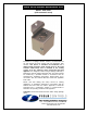
The GSK-160A is a normally closed single-pole, single throw (SPST)
thermally-activated switch that is intended to be wired in series with the
burner control safety circuit of an 80+ efficiency-rated, fan-assisted, gas-
fired appliance. When subjected to temperatures above approximately
160°F, the switch will open, interrupting the safety circuit, thereby
preventing the burner from firing. When allowed to cool, the switch will
automatically reset, allowing the burner to fire. Activation of the GSK switch
may cause burner lockout on some appliances.
INSTALLATION ON DRAFT CONTROLS:
NOTE: GSK style switches are designed for mounting on draft control
models 4” MG1 through 9” MG1. Larger size draft controls required the FTS
series switches.
U
NIT WITH MG1 DRAFT CONTROL SUPPLIED WITH GSK IN A KIT:
1. Mount the switch onto the threaded stud on the top front of the
MG1, using the supplied 8-32 locking nut.
2. Swing the gate in and out to verify smooth operation through the range of
operation.
U
NIT WITH DRAFT CONTROL SUPPLIED SEPARATELY:
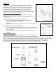
1. Mount the switch with the supplied #5-40 machine screw and nut on the top
front of the MG1. (Note, the head of the screw is to be on the inside of the
ring. (See Figure 2)
2. Swing the gate in and out to verify smooth operation through the range of
operation.
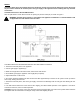
INSTALLATION LOCATION:
For single-appliance venting applications, install the draft control with GSK-160A
directly above the appliance as shown in Figure 3, unless otherwise instructed by the
appliance manufacturer. For co-venting applications with an atmospheric-burner-equipped appliance (such as a water
heater), install the draft control with GSK-160A immediately below the tee or wye fitting, as shown by the dashed lines in
the figure, to help prevent spillage at the water heater. A Field Controls Barohood
TM
with one GSK-3 mounted
(recommended) or two GSK-3 spill switches mounted on the draft hood (available in kit SSK-1), wired into the
thermocouple circuit (use one TCA-1 for either method) is recommended for additional safety.
Figure 1
Figure 2