
Overview of Primary Product
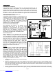


GENERAL SYSTEM OPERATION
1. The thermostat (wall thermostat, or aquastat) calls for heat and energizes a relay which activates the CAS unit. After
the CAS fan has come up to speed, an internal air pressure switch closes and completes the circuit to allow the
burner to fire. If the appliance is power vented, the venter and will typically activate before the CAS unit..
2. After the heating requirement has been satisfied, the thermostat circuit will open and deactivate the burner and CAS
unit.
3. For power vented systems with a post purge device, the power venter will operate for a period of time determined by
the post purge timer setting after the burner has shut off to purge remaining flue gases from the vent system.
INSTALLATION SAFETY INSTRUCTIONS
CAUTION: This device must be installed by a qualified installer in accordance with the manufacturer's installation
instructions.
1. This combustion air system must be installed by a qualified installer. "Qualified Installer" shall mean an individual who
has been properly trained or a licensed installer.
2. Plan the system layout before installation to avoid the possibility of accidental contact with concealed wiring or
plumbing inside walls.
3. Disconnect power supply before making wiring connections to prevent electrical shock and equipment damage.
SIZING AND SETUP
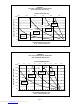
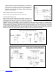
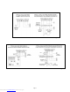
Diagram A shows the maximum equivalent length and size of duct pipe that should be used when installing the CAS-6
system; Diagram B shows the same for the CAS-7. Using this table will help ensure that the proper amount of air is drawn
into the structure as needed by the appliance. The defined regions shown correspond to the CAS's airflow characteristics
when using various sizes of duct pipe for the CAS-6 and CAS-7. Follow the guidelines below to properly size and set up
the CAS system.
1. Determine the input firing rate of the appliance, or the total firing rate of multiple appliances that will be used.
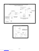
2. Determine the location of the CAS unit according to the guidelines in the "Installation" section.
3. Determine where the intake air StarKap will be located based on the recommendations in the "Installation" section.
4. On Diagram A or B (as appropriate), locate the point that corresponds to the firing rate along the horizontal axis and
draw a vertical line through this point.
5. The line should pass through at least one of the pipe size regions on the table. The regions correspond to the
maximum equivalent lengths of the given diameter duct pipe that will be adequately sized for the application.
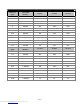
6. Calculate the equivalent length of the smaller diameter duct pipe that may be used with the particular CAS system,
including elbows, reducer/increaser and other fittings (except the StarKap, see page 32 of the Field Controls
Contractor Reference Guide). The effects of the StarKap are already figured into the diagram, so do not attempt
to include any value for the StarKap in your calculation for equivalent length. Draw a horizontal line through the point
corresponding to the equivalent length on the vertical axis.
7. Locate the intersection of the two drawn lines. If the intersection lies in the region for the equivalent length of pipe for
which the equivalent length was calculated, then that diameter of duct pipe will be of sufficient size for the application.
If not, then repeat step 7 using a larger diameter duct, then proceed to step 9.
8. If the intersection of the two lines falls into the larger duct region, then that diameter duct will be of sufficient size for
the application. If it falls to the right of the larger pipe region, then even larger pipe or additional CAS units will be
required for the application. For assistance in this case, call Field Controls Technical Support at 1-800-742-8368.
Example: An oil fired appliance firing at 10.5 gph where a CAS-7 unit needs to be placed at a location requiring 80 feet of
pipe from the StarKap, using two 90 degree elbows:
From Diagram B, a vertical line is drawn through the point at 10.5 gph on the "Oil Firing Rate" scale. For 80 feet of 10”
pipe, two 90 degree elbows, and two increaser/ reducers, the equivalent length is 80 + 18 + 18 + 6 + 6 = 128 feet of
equivalent length. A horizontal line drawn through the point at 128 feet on the “Equivalent Length” scale intersects the
vertical line in the 12” duct region of the diagram. Since the intersection is not in the 10” duct region, recalculate the
equivalent length using 12” duct: 80 + 21 + 21 + 7 + 7 = 136 feet of equivalent length. A horizontal line drawn through the
136 point on the “Equivalent Length” scale intersects the vertical line within the 12” duct region of the diagram; therefore,
12” duct will be of sufficient size for the application.
Page 2
Downloaded from www.Manualslib.com manuals search engine