
Overview of Primary Product


page 11
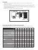
INITIAL BURNER AND VENTING SYSTEM OPERATIONAL INFORMATION
List the following for each operating appliance on the sidewall venting system, as a guide for tune-up or
service information annually.
DATE:
FOR GAS FIRED EQUIPMENT
Heating Appliance BTU/HR Input
Gas Valve Operation Pressure
Vent System Draft Above Draft Hood or
Before Barometric Draft Control
CO
2
Measurement
CO Measurement
Equipment Outlet Flue Gas Temperature
FOR OIL FIRED EQUIPMENT
Oil Burner Nozzle Size
Oil Burner Operating Pressure
Pump Operating Vacuum Pressure
Smoke Number
Over-fire Draft
Equipment Outlet Flue Gas Temperature
CO
2
Measurement
INSTALLATION
Align the holes in the circular cover plate with the holes in the motor mount bracket on the motor 1.
assembly. (See Figure 16)
Slide the motor assembly onto the protruding threaded studs on the power venter body with the exhaust 2.
chute pointing downward, and replace the four nuts securely to the threaded studs. (See Figure 16)
Re-attach wires and wire nuts to the motor wiring and reinstall the conduit connector, firmly tightening the 3.
screw on the side of the connector.
Install the motor cover with the side louvers pointing downward.4.
Figure 16