
Overview of Primary Product


page 3
PROCEDURE FOR CALCULATING TOTAL EQUIVALENT PIPE LENGTH IN FEET
Calculate the total equivalent feet for each type of fitting used in the venting system from the chart below.1.
Calculate the total amount of feet for the straight lengths of vent pipe.2.
Add the equivalent feet for the fitting with the total amount of feet of straight lengths. This will approximate the 3.
total equivalent feet of the vent system.
UNIT SIZING CHART
OIL GAS
MAXIMUM EQUIVALENT FEET OF
VENT PIPE
MAX* OIL
GPH INPUT
MAX** BTU/
HR INPUT
AT MAX BTU/
HR INPUT
AT 60% OF MAX
BTU/HR INPUT
VENTING WITH VENT
PIPE SIZE
MODEL
1.10 170,000
--- 23 3"
CV-435 100 4"
65 100 5"
1.85 290,000
16 44 4"
CV-551 100 5"
95 100 6"
EQUIVALENT LENGTH (FEET) OF VENT PIPE FOR VENT PIPE FITTING
VENT PIPE FITTINGS
VENT PIPE DIAMETER
3" 4" 5" 6" 7" 8" 9" 10"
TEE 19 25 31 38 44 50 56 63
90º ELBOW 5 7 9 11 12 14 16 18
45º ELBOW 3 4 4 5 6 7 8 9
SUDDEN REDUCER
OR INCREASER
FOR 3 *RATIOS (d/D)
d
⁄D
1
⁄4 8 11 14 17 19 22 25 28
1
⁄2 5 7 8 10 12 13 15 17
3
⁄4 2 3 3 4 4 5 6 6
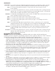
*Reducer or increaser ratio (d/D) small diameter divided reducer ratio is d/D =
4
⁄8 =
1
⁄2. To
estimate the equivalent foot length for the fitting, use the smaller pipe diameter for the equivalent
length figure. Example 4" to 8" reducer; the reducer ratio is
1
⁄2 and the smaller pipe diameter is
4". So, from the chart, the equivalent feet would be 7 feet. (See Figure 1)
Figure 1
On oil-fired and gas-fired heating appliances not equipped with a draft hood, a barometric draft control 9.
MUST be installed to regulate proper air flow and fluctuations in the system's air flow during operation.
Fluctuations may come from wind loads on the outlet of the power venter, house de-pressurization during
windy days, and the different house ventilation requirements between summer and winter operation. For
gas appliances, use a Field Controls Type MG-1 Barometric Draft Control. For oil appliances, use a Field
Controls Type M or RC Barometric Draft Control. Gas-fired draft induced systems should have a single-
acting barometric draft control installed.
INSTALLATION OF SWG POWER VENTER (See Table 1)
Table 1
*Rating at 100 psi. Sizing based on appliance maximum input rate not actual firing rate. **Do not exceed maximum BTU/HR input
rating or maximum oil GPH input. For multiple venting system applications, add the input for each appliance. Category I gas-fired
draft induced systems require a CV-4 or larger. Category III gas-fired draft induced systems require a CV-5 or larger.
Table 2
Example: System Pipe Size = 4”
Step 1 Two 4” 90° elbows @ 7 feet each = 14 ft.
Step 2 Ten 2 foot lengths of 4” pipe = 20 ft.
Step 3 Total equivalent feet = 14 ft. + 20 ft. = 34 ft.