
Overview of Primary Product


page 6
VENTING SYSTEM CONNECTIONS
Venting system should be installed and
supported in accordance with the National
Fuel Gas Code ANSI Z223.1, or in
accordance with any local codes. A vent
pipe connector shall be supported for the
design and weight of the material employed,
to maintain clearances, prevent physical
damage, and separation of joints. A vent
pipe increaser or reducer may be required
for connecting the power venter to the vent
system. If needed, place the reducer close to
the power venter. Smaller vent pipe sizes than
a chimney-vented system may be used for the
vent system.
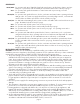
If mounting venting system near combustible
materials, refer to Diagram B for allowable
venting system installation clearances.
Clearances are based on an installation
using single wall galvanized steel vent pipe.
For metal thickness of galvanized steel pipe
connectors, refer to NFPA 211 or NFPA 54 Standards for guidelines. If manufactured double wall
vent pipe is required or used for the installation, clearance should be based on the vent pipes rated
clearance. Always check local code requirements for code restrictions.
Route the vent pipe from the appliance to the power venter using as few elbows as possible. The horizontal
section of the vent pipe should have a slight upward slope from the appliance to the power venter. For
clearances to combustible materials, multiple appliance venting, and other installation requirements, refer to
the National Fuel Gas Code ANSI Z223.1, and/or any applicable local codes or appliance manufacturer’s
installation instructions.
Diagram B
Figure 9
WARNING: If the venter does not supply combustion air to an appliance, the factory-installed air tee cover
plate must be in place on the venter. Fire hazard and/or infiltration of vented gases may occur if the cover
plate is not in place on the venter.
WARNING: The combustion air feature must be connected to one appliance only.